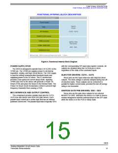
FUNCTIONAL DEVICE OPERATION
OPERATIONAL MODES
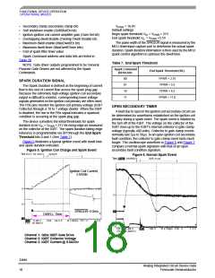
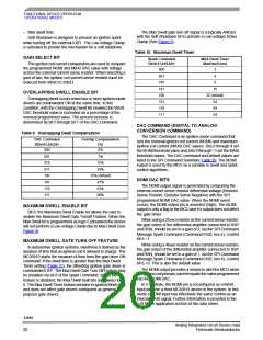
The Low-voltage Clamp spreads out the energy
dissipation over a longer period of time, thus allowing the use
of a lower energy rated IGBTs. The internal low-voltage
clamp is connected between the IGBT's collector (through an
external resistor) and the IGBT's gate. The energy stored in
the ignition coil is dissipated by the IGBT, not the internal
clamp. The internal clamp only provides the bias to the IGBT.
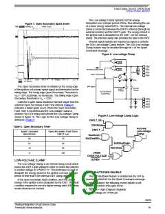
Figure 7. Open Secondary Spark Event
Several logical signals are required as inputs to activate
the GDx Low-voltage Clamp feature. The GDx Low-voltage
Clamp feature may be disabled through bit 4 of the Spark
Command message.
Figure 8. Low-voltage Clamp
+
–
SPI
FB0
FB1
FB2
FB3
+
–
SPARK DURATION
Open Secondary
SPI
100µA
53V
+
−
V
PWR
13V
SPI input
The Open Secondary timer is initiated on the rising edge
of the ignition coil primary spark signal and terminated on the
falling edge. The rising edge Open Secondary Threshold is
VIH= 135V at primary, no hysteresis. The falling edge Open
Secondary threshold is VIL = 135V.
GPGD
Clamp
Low V
Clamp
GATE DRIVE
CONTROL
GD0
GD1
GD2
GD3
Collector to gate clamp durations that last longer than the
selected Open Secondary Fault Time interval (Table 8)
indicates a failed spark event. When the Open Secondary
Fault Time is exceeded and the Low-voltage Clamp is
enabled, the GDx output will activate the Low-voltage Clamp
shown in figure 16. The Logic for this Low-voltage Clamp is
defined in Figure 9
Figure 9. Low-voltage Clamp Logic
OSFLT_En
IGN Mode
OSFLT
Table 8. Open Secondary Timer
Activate
Low-voltage
Clamp
Spark Command
Bits<b3,b2>
Open Secondary Fault Timer
OSFLT (µs)
MaxDwell
MaxDwellEn
00
01
10
11
10
20
SoftShutDnEn
IGN Mode
50
100
VPWR
OVER-VOLTAGE
OUTEN
LOW-VOLTAGE CLAMP
The Low-voltage Clamp is an internal clamp circuit which
biases the IGBT's gate voltage in order to control the collector
to emitter voltage to VPWR+11V. This technique is used to
dissipate the energy stored in the ignition coil over a longer
period of time than if the internal IGBT clamp were used.
SOFT SHUTDOWN ENABLE
The soft shutdown feature is enabled via the SPI by
asserting control bit 5 in the Spark Command message.
In the open secondary fault condition, all of the stored
energy in the ignition coil is dissipated by the IGBT. This fault
condition requires the use of a higher energy rated IGBT than
would otherwise be needed.
When enabled, the following events initiate a soft
shutdown control of the gate driver.
• OUTEN = High (Outputs Disabled)
• Over-voltage on VPWR pin
33810
Analog Integrated Circuit Device Data
Freescale Semiconductor
19

 FREESCALE [ Freescale ]