External Memory Expansion Port (Port A)
3.10.2 DRAM Timing
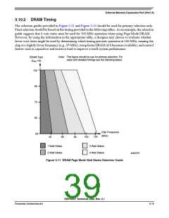
The selection guides provided in Figure 3-11 and Figure 3-14 should be used for primary selection only.
Final selection should be based on the timing provided in the following tables. As an example, the selection
guide suggests that 4 wait states must be used for 100 MHz operation when using Page Mode DRAM.
However, by using the information in the appropriate table, a designer may choose to evaluate whether
fewer wait states might be used by determining which timing prevents operation at 100 MHz, running the
chip at a slightly lower frequency (e.g., 95 MHz), using faster DRAM (if it becomes available), and control
factors such as capacitive and resistive load to improve overall system performance.
Note: This figure should be use for primary selection. For
exact and detailed timings see the following tables.
DRAM Type
(tRAC ns)
100
80
70
60
Chip Frequency
(MHz)
50
120
40
66
80
100
1 Wait States
2 Wait States
3 Wait States
4 Wait States
AA0472
Figure 3-11 DRAM Page Mode Wait States Selection Guide
DSP56367 Technical Data, Rev. 2.1
Freescale Semiconductor
3-15

 FREESCALE [ Freescale ]