Freescale Semiconductor, Inc.
3. INTRST (internal reset) goes to all other internal circuits.
Synchronous reset sources are not asserted until the end of the current bus cycle,
whether or not RMC is asserted. The internal bus monitor is automatically enabled for
synchronous resets; therefore, if the current bus cycle does not terminate normally, the
bus monitor terminates it. Only single-byte or word transfers are guaranteed valid for
synchronous resets. An external or clock reset is a synchronous reset source.
Asynchronous reset sources indicate a catastrophic failure, and the reset controller logic
immediately resets the system. Resetting the MC68340 causes any bus cycle in progress
to terminate as if DSACK≈ or BERR had been asserted. In addition, the MC68340
appropriately initializes registers for a reset exception. Asynchronous reset sources
include power-up, software watchdog, double bus fault resets, and execution of the
RESET instruction.
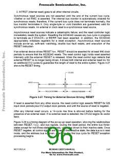
If an external device drives RESET low, RESET should be asserted for at least 590 clock
periods to ensure that the MC68340 resets. The reset control logic holds reset asserted
internally until the external RESET is released. When the reset control logic detects that
external RESET is no longer being driven, it drives both internal and external reset low for
an additional 512 cycles to guarantee this length of reset to the entire system. Figure 3-27
shows the RESET timing.
1 CLOCK
RESET
590 CLOCK
512 CLOCK
PULLED EXTERNAL
DRIVEN BY MC68340
Figure 3-27. Timing for External Devices Driving RESET
If reset is asserted from any other source, the reset control logic asserts RESET for 328
input clock periods plus 512 output clock periods, and until the source of reset is negated.
After any internal reset occurs, a 14-cycle rise time is allowed before testing for the
presence of an external reset. If no external reset is detected, the CPU32 begins its vector
fetch.
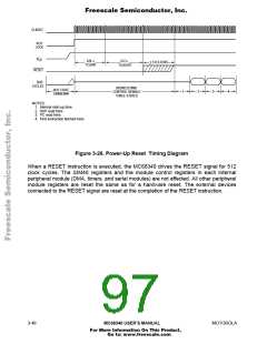
Figure 3-28 is a timing diagram of the power-up reset operation, showing the relationships
between RESET, V
, and bus signals. During the reset period, the entire bus three-
CC
states except for non-three-statable signals, which are driven to their inactive state. Once
RESET negates, all control signals are driven to their inactive state, the data bus is in read
mode, and the address bus is driven. After this, the first bus cycle for RESET exception
processing begins.
MOTOROLA
MC68340 USER’S MANUAL
3- 47
For More Information On This Product,
Go to: www.freescale.com

 FREESCALE [ Freescale ]