Freescale Semiconductor, Inc.
Development Support
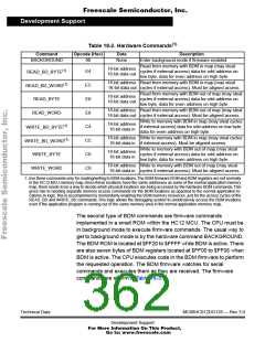
Table 18-2. Hardware Commands(1)
Command
Opcode (Hex)
Data
Description
BACKGROUND
90
None
Enter background mode if firmware enabled.
Read from memory with BDM in map (may steal
cycles if external access) data for odd address on
low byte, data for even address on high byte.
16-bit address
16-bit data out
READ_BD_BYTE(1)
READ_BD_WORD(1)
READ_BYTE
E4
16-bit address Read from memory with BDM in map (may steal
16-bit data out cycles if external access). Must be aligned access.
EC
E0
E8
C4
CC
C0
C8
Read from memory with BDM out of map (may steal
16-bit address
cycles if external access) data for odd address on
16-bit data out
low byte, data for even address on high byte.
16-bit address Read from memory with BDM out of map (may steal
16-bit data out cycles if external access). Must be aligned access.
READ_WORD
Write to memory with BDM in map (may steal cycles
16-bit address
WRITE_BD_BYTE(1)
WRITE_BD_WORD(1)
WRITE_BYTE
if external access) data for odd address on low byte,
16-bit data in
data for even address on high byte.
16-bit address Write to memory with BDM in map (may steal cycles
16-bit data in if external access). Must be aligned access.
Write to memory with BDM out of map (may steal
16-bit address
cycles if external access) data for odd address on
16-bit data in
low byte, data for even address on high byte.
16-bit address Write to memory with BDM out of map (may steal
16-bit data in cycles if external access). Must be aligned access.
WRITE_WORD
1. Use these commands only for reading/writing to BDM locations
in the HC12 MCU memory map Since these locations have the same addresses as some of the normal application memory
map, there needs to be a way to decide which physical locations are being accessed by the hardware BDM commands This
gives rise to needing separate memory access commands for the BDM locations as opposed to the normal application lo-
cations In logic, this is accomplished by momentarily enabling the BDM memory resources, just for the access cycles of the
READ_BD and WRITE_BD commands This logic allows the debugging system to unobtrusively access the BDM locations
even if the application program is running out of the same memory area in the normal application memory map
.
The BDM firmware ROM and BDM registers are not normally
.
.
.
.
.
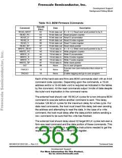
The second type of BDM commands are firmware commands
implemented in a small ROM within the HC12 MCU. The CPU must be
in background mode to execute firmware commands. The usual way to
get to background mode is by the hardware command BACKGROUND.
The BDM ROM is located at $FF20 to $FFFF while BDM is active. There
are also seven bytes of BDM registers located at $FF00 to $FF06 when
BDM is active. The CPU executes code in the BDM firmware to perform
the requested operation. The BDM firmware watches for serial
commands and executes them as they are received. The firmware
commands are shown in Table 18-3.
Technical Data
MC68HC912DG128 — Rev 3.0
Development Support
For More Information On This Product,
Go to: www.freescale.com

 FREESCALE [ Freescale ]