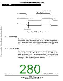
Freescale Semiconductor, Inc.
Inter-IC Bus
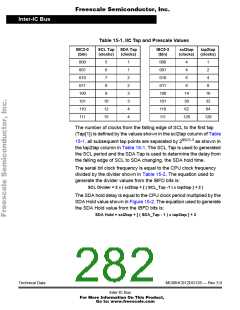
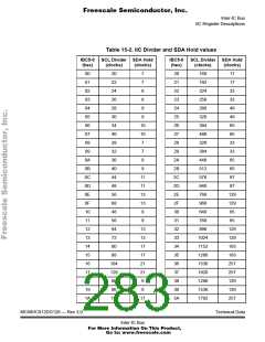
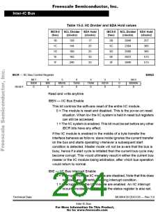
Table 15-2. IIC Divider and SDA Hold values
IBC5-0
(hex)
SCL Divider SDA Hold
IBC5-0
(hex)
SCL Divider SDA Hold
(clocks)
(clocks)
(clocks)
(clocks)
1B
1C
1D
1E
1F
128
17
3B
3C
3D
3E
3F
2048
257
144
25
2304
385
160
25
2560
385
192
33
3072
513
240
33
3840
513
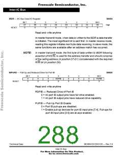
IBCR — IIC Bus Control Register
$00E2
Bit 7
IBEN
0
6
IBIE
0
5
MS/SL
0
4
3
TXAK
0
2
1
0
0
Bit 0
Tx/Rx
RSTA
0
IBSWAI
0
RESET:
0
Read and write anytime
IBEN — IIC Bus Enable
This bit controls the software reset of the entire IIC module.
0 = The module is reset and disabled. This is the power-on reset
situation. When low the IIC system is held in reset but registers
can still be accessed.
1 = The IIC system is enabled. This bit must be set before any other
IBCR bits have any effect.
If the IIC module is enabled in the middle of a byte transfer the
interface behaves as follows: slave mode ignores the current transfer
on the bus and starts operating whenever a subsequent start
condition is detected. Master mode will not be aware that the bus is
busy, hence if a start cycle is initiated then the current bus cycle may
become corrupt. This would ultimately result in either the current bus
master or the IIC module losing arbitration, after which bus operation
would return to normal.
IBIE — IIC Bus Interrupt Enable
0 = Interrupts from the IIC module are disabled. Note that this does
not clear any currently pending interrupt condition.
1 = Interrupts from the IIC module are enabled. An IIC interrupt
occurs provided the IBIF bit in the status register is also set.
Technical Data
MC68HC912DG128 — Rev 3.0
Inter-IC Bus
For More Information On This Product,
Go to: www.freescale.com

 FREESCALE [ Freescale ]