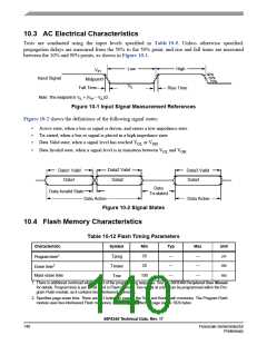
10.3 AC Electrical Characteristics
Tests are conducted using the input levels specified in Table 10-5. Unless otherwise specified,
propagation delays are measured from the 50% to the 50% point, and rise and fall times are measured
between the 10% and 90% points, as shown in Figure 10-1.
Low
VIL
High
VIH
90%
50%
10%
Input Signal
Midpoint1
Fall Time
Note: The midpoint is VIL + (VIH – VIL)/2.
Rise Time
Figure 10-1 Input Signal Measurement References
Figure 10-2 shows the definitions of the following signal states:
•
•
•
Active state, when a bus or signal is driven, and enters a low impedance state
Tri-stated, when a bus or signal is placed in a high impedance state
Data Valid state, when a signal level has reached VOL or VOH
•
Data Invalid state, when a signal level is in transition between VOL and VOH
Data2 Valid
Data2
Data1 Valid
Data1
Data3 Valid
Data3
Data
Tri-stated
Data Invalid State
Data Active
Data Active
Figure 10-2 Signal States
10.4 Flash Memory Characteristics
Table 10-12 Flash Timing Parameters
Characteristic
Symbol
Tprog
Terase
Tme
Min
20
Typ
—
Max
—
Unit
μs
Program time1
Erase time2
20
—
—
ms
ms
Mass erase time
100
—
—
1. There is additional overhead which is part of the programming sequence. See the 56F8300 Peripheral User Manual
for details. Program time is per 16-bit word in Flash memory. Two words at a time can be programmed within the Pro-
gram Flash module, as it contains two interleaved memories.
2. Specifies page erase time. There are 512 bytes per page in the Data and Boot Flash memories. The Program Flash
module uses two interleaved Flash memories, increasing the effective page size to 1024 bytes.
56F8345 Technical Data, Rev. 17
140
Freescale Semiconductor
Preliminary

 FREESCALE [ Freescale ]