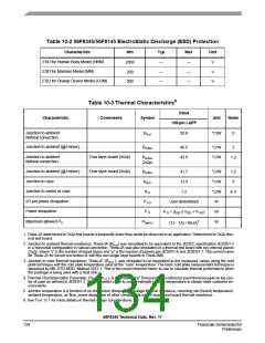
Table 10-2 56F8345/56F8145 ElectroStatic Discharge (ESD) Protection
Characteristic
Min
Typ
Max
Unit
ESD for Human Body Model (HBM)
ESD for Machine Model (MM)
ESD for Charge Device Model (CDM)
2000
200
—
—
—
—
—
—
V
V
V
500
6
Table 10-3 Thermal Characteristics
Value
Characteristic
Comments
Symbol
Unit
Notes
128-pin LQFP
Junction to ambient
R
50.8
°C/W
2
θJA
Natural convection
Junction to ambient (@1m/sec)
R
46.5
43.9
°C/W
°C/W
2
θJMA
Junction to ambient
Natural convection
Four layer board (2s2p)
Four layer board (2s2p)
R
1,2
θJMA
(2s2p)
Junction to ambient (@1m/sec)
Junction to case
R
41.7
13.9
°C/W
°C/W
°C/W
W
1,2
3
θJMA
R
θJC
Junction to center of case
I/O pin power dissipation
Power dissipation
Ψ
1.2
4, 5
JT
P
User-determined
P D = (IDD x VDD + P I/O
I/O
P
)
W
D
(TJ - TA) / RθJA7
Maximum allowed PD
P
W
DMAX
1. Theta-JA determined on 2s2p test boards is frequently lower than would be observed in an application. Determined on 2s2p ther-
mal test board.
2. Junction to ambient thermal resistance, Theta-JA (R ) was simulated to be equivalent to the JEDEC specification JESD51-2
θJA
in a horizontal configuration in natural convection. Theta-JA was also simulated on a thermal test board with two internal planes
(2s2p, where “s” is the number of signal layers and “p” is the number of planes) per JESD51-6 and JESD51-7. The correct name
for Theta-JA for forced convection or with the non-single layer boards is Theta-JMA.
3. Junction to case thermal resistance, Theta-JC (R
), was simulated to be equivalent to the measured values using the cold
θJC
plate technique with the cold plate temperature used as the "case" temperature. The basic cold plate measurement technique is
described by MIL-STD 883D, Method 1012.1. This is the correct thermal metric to use to calculate thermal performance when
the package is being used with a heat sink.
4. Thermal Characterization Parameter, Psi-JT (Ψ ), is the "resistance" from junction to reference point thermocouple on top cen-
JT
ter of case as defined in JESD51-2. Ψ is a useful value to use to estimate junction temperature in steady-state customer en-
JT
vironments.
5. Junction temperature is a function of on-chip power dissipation, package thermal resistance, mounting site (board) temperature,
ambient temperature, air flow, power dissipation of other components on the board, and board thermal resistance.
6. See Part 12.1 for more details on thermal design considerations.
56F8345 Technical Data, Rev. 17
134
Freescale Semiconductor
Preliminary

 FREESCALE [ Freescale ]