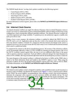
Ceramic Resonator
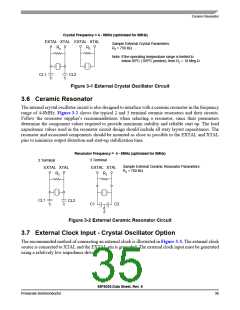
Crystal Frequency = 4 - 8MHz (optimized for 8MHz)
EXTAL XTAL
Rz
EXTAL XTAL
Rz
Sample External Crystal Parameters:
Rz = 750 KΩ
Note: If the operating temperature range is limited to
below 85oC (105oC junction), then Rz = 10 Meg Ω
CL1
CL2
Figure 3-1 External Crystal Oscillator Circuit
3.6 Ceramic Resonator
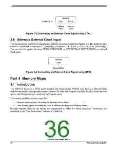
The internal crystal oscillator circuit is also designed to interface with a ceramic resonator in the frequency
range of 4-8MHz. Figure 3-2 shows the typical 2 and 3 terminal ceramic resonators and their circuits.
Follow the resonator supplier’s recommendations when selecting a resonator, since their parameters
determine the component values required to provide maximum stability and reliable start up. The load
capacitance values used in the resonator circuit design should include all stray layout capacitances. The
resonator and associated components should be mounted as close as possible to the EXTAL and XTAL
pins to minimize output distortion and start-up stabilization time.
Resonator Frequency = 4 - 8MHz (optimized for 8MHz)
3 Terminal
2 Terminal
EXTAL XTAL
Rz
Sample External Ceramic Resonator Parameters:
Rz = 750 KΩ
EXTAL XTAL
Rz
CL1
CL2
C1
C2
Figure 3-2 External Ceramic Resonator Circuit
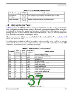
3.7 External Clock Input - Crystal Oscillator Option
The recommended method of connecting an external clock is illustrated in Figure 3-3. The external clock
source is connected to XTAL and the EXTAL pin is grounded. The external clock input must be generated
using a relatively low impedance driver.
56F8036 Data Sheet, Rev. 6
Freescale Semiconductor
35

 FREESCALE [ Freescale ]