5.6.6
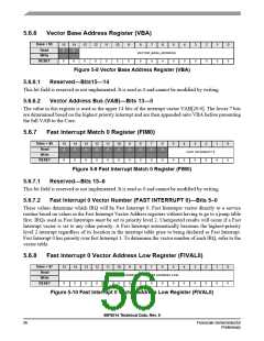
Vector Base Address Register (VBA)
Base + $5
Read
15
0
14
0
13
12
11
10
9
8
7
6
5
4
0
3
0
2
0
1
0
0
0
VECTOR_BASE_ADDRESS
Write
RESET
0
0
0
0
0
0
0
0
0
0
0
Figure 5-8 Vector Base Address Register (VBA)
5.6.6.1
Reserved—Bits15—14
This bit field is reserved or not implemented. It is read as 0 and cannot be modified by writing.
5.6.6.2
Vector Address Bus (VAB)—Bits 13—0
The value in this register is used as the upper 14 bits of the interrupt vector VAB[20:0]. The lower 7 bits
are determined based on the highest priority interrupt and are then appended onto VBA before presenting
the full VAB to the Core.
5.6.7
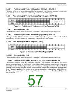
Fast Interrupt Match 0 Register (FIM0)
Base + $6
Read
15
0
14
0
13
0
12
0
11
0
10
0
9
0
8
0
7
0
6
0
5
0
4
0
3
2
1
0
0
0
FAST INTERRUPT 0
Write
0
0
0
0
0
0
0
0
0
0
0
0
RESET
Figure 5-9 Fast Interrupt Match 0 Register (FIM0)
5.6.7.1
Reserved—Bits 15–6
This bit field is reserved or not implemented. It is read as 0 and cannot be modified by writing.
5.6.7.2
Fast Interrupt 0 Vector Number (FAST INTERRUPT 0)—Bits 5–0
These values determine which IRQ will be Fast Interrupt 0. Fast Interrupts vector directly to a service
routine based on values in the Fast Interrupt Vector Address registers without having to go to a jump table
first. IRQs used as Fast Interrupts must be set to priority level 2. Unexpected results will occur if a Fast
Interrupt vector is set to any other priority. A Fast Interrupt automatically becomes the highest-priority
level 2 interrupt regardless of its location in the interrupt table prior to being declared as Fast Interrupt.
Fast Interrupt 0 has priority over fast Interrupt 1. To determine the vector number of each IRQ, refer to the
vector table.
5.6.8
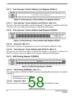
Fast Interrupt 0 Vector Address Low Register (FIVAL0)
Base + $7
Read
15
14
13
12
11
10
9
8
7
6
5
4
3
2
0
1
0
0
0
FAST INTERRUPT 0 VECTOR ADDRESS LOW
Write
RESET
0
0
0
0
0
0
0
0
0
0
0
0
0
Figure 5-10 Fast Interrupt 0 Vector Address Low Register (FIVAL0)
56F8014 Technical Data, Rev. 9
56
Freescale Semiconductor
Preliminary

 FREESCALE [ Freescale ]