10.8 Reset, Stop, Wait, Mode Select, and Interrupt Timing
Note: All the address and data buses described here are internal.
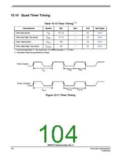
1,2
Table 10-13 Reset, Stop, Wait, Mode Select, and Interrupt Timing
Characteristic
Symbol
tRA
Typical Min
Typical Max
Unit
ns
See Figure
10-6
Minimum RESET Assertion Duration
Minimum GPIO pin Assertion for Interrupt
4T
2T
—
—
tIW
ns
RESET deassertion to First Address Fetch3
tRDA
tIF
96TOSC + 64T 97TOSC + 65T
6T
ns
Delay from Interrupt Assertion to Fetch of first
instruction (exiting Stop)
—
ns
1. In the formulas, T = clock cycle and T
= oscillator clock cycle. For an operating frequency of 32MHz, T = 31.25ns. At 8MHz
osc
(used during Reset and Stop modes), T = 125ns.
2. Parameters listed are guaranteed by design.
3. During Power-On Reset, it is possible to use the 56F8014 internal reset stretching circuitry to extend this period to 2^21T.
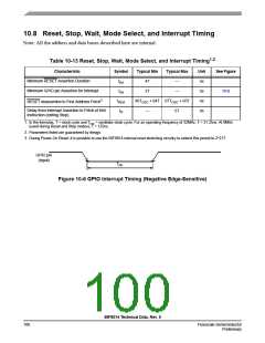
GPIO pin
(Input)
TIW
Figure 10-6 GPIO Interrupt Timing (Negative Edge-Sensitive)
56F8014 Technical Data, Rev. 9
100
Freescale Semiconductor
Preliminary

 FREESCALE [ Freescale ]