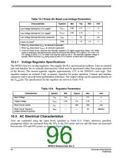
Table 10-7 Power-On Reset Low-Voltage Parameters
Typ
2.7
Max
—
Unit
V
Min
2.60
2.05
—
Characteristic
Symbol
VEI3.3
VE12.5
VEIH
Low-Voltage Interrupt for 3.3V supply1
Low-Voltage Interrupt for 2.5V supply2
2.15
50
—
V
Low-Voltage Interrupt Recovery Hysteresis
—
mV
V
Power-On Reset3
POR
—
1.8
1.9
1. When V drops below V
, an interrupt is generated.
DD
EI3.3
2. When V drops below V
, an interrupt is generated.
DD
EI32.5
3. Power-On Reset occurs whenever the internally regulated 2.5V digital supply drops below 1.8V. While
power is ramping up, this signal remains active for as long as the internal 2.5V is below 2.15V or the 3.3V
1/O voltage is below 2.7V, no matter how long the ramp-up rate is. The internally regulated voltage is
typically 100mV less than V during ramp-up until 2.5V is reached, at which time it self-regulates.
DD
10.2.1 Voltage Regulator Specifications
The 56F8014 has two on-chip regulators. One supplies the PLL and relaxation oscillator. It has no external
pins and therefore has no external characteristics which must be guaranteed (other than proper operation
of the device). The second regulator supplies approximately 2.5V to the 56F8014’s core logic. This
regulator requires an external 4.4μF, or greater, capacitor for proper operation. Ceramic and tantalum
capacitors tend to provide better performance tolerances. The output voltage can be measured directly on
the V
pin. The specifications for this regulator are shown in Table 10-8.
CAP
Table 10-8. Regulator Parameters
Characteristic
Symbol
VIN
Min
3.0
2.25
—
Typical
—
Max
3.6
Unit
V
Input Voltage
Output Voltage
VOUT
ISS
2.5
2.75
650
30
V
Short Circuit Current
450
—
mA
Short Circuit Tolerance
TRSC
—
Minutes
(output shorted to ground)
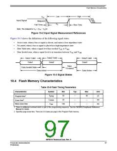
10.3 AC Electrical Characteristics
Tests are conducted using the input levels specified in Table 10-5. Unless otherwise specified,
propagation delays are measured from the 50% to the 50% point, and rise and fall times are measured
between the 10% and 90% points, as shown in Figure 10-2.
56F8014 Technical Data, Rev. 9
96
Freescale Semiconductor
Preliminary

 FREESCALE [ Freescale ]