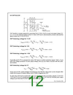
6. BLOCK DESCRIPTION & APPLICATION INFORMATIONS
6.1 OSCILLATOR BLOCK
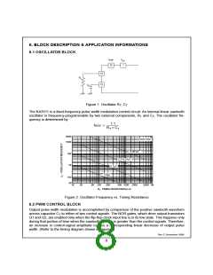
Vref
12
VCC
1
12
12
RT
CT
Figure 1. Oscillator RT, CT
The KA3511 is a fixed-frequency pulse width modulation control circuit. An internal-linear sawtooth
oscillator is frequency-programmable by two external components, RT and CT. The oscillator fre-
quency is determined by
1.1
= --------------------
fosc
×
RT CT
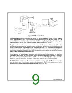
300K
100K
VCC=15V
0.001µF
10K
1K
CT=0.01µF
0.1µF
1.0µF
100
30
1K
2K
5K 10K
20K
50K 100K 200K
500K 1M
RT. TIMING RESISTANCE( Ω)
Figure 2. Oscillator Frequency vs. Timing Resistance
6.2 PWM CONTROL BLOCK
Output pulse width modulation is accomplished by comparison of the positive sawtooth waveform
across capacitor CT to either of two control signals. The NOR gates, which drive output transistors
Q1 and Q2, are enabled only when the flip-flop clock-input line is in its low state. This happens only
during that portion of time when the sawtooth voltage is greater than the control signals. Therefore,
an increase in control-signal amplitude causes a corresponding linear decrease of output pulse
width. (Refer to the timing diagram shown in Figure 4)
Rev C, November 1999
8

 FAIRCHILD [ FAIRCHILD SEMICONDUCTOR ]