RT
CT
7
8
OSCILLATOR
Output
Drive
Q1
Q2
D
Q
Q
2
CK
PWM
CONTROL
COMP
4
3
0.12V
DEAD TIME
CONTROLLER
1.25V
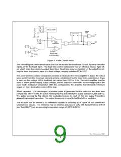
Figure 3. PWM Control Block
The control signals are external inputs that can be fed into the dead-time control, the error amplifier
inputs, or the feedback input. The dead-time control comparator has an effective 120mV input off-
set which limits the minimum output dead time. Dead time may be imposed on the output by set-
ting the dead time control input to a fixed voltage, ranging between 0V to 3.3V.
The pulse width modulator comparator provides a means for the error amplifier to adjust the output
pulse width from the maximum percent on-time, established by the dead time control input, down
to zero, as the voltage at the feedback pin varies from 0.5V to 3.5V. The error amplifier may be
used to sense power-supply output voltage, and its output is connect to noninverting input of the
pulse width modulator comparator. With this configuration, the amplifier that demands minimum
output on time, dominates control of the loop.
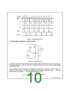
When capacitor CT is discharged, a positive pulse is generated on the output of the dead time
comparator, which clocks the pulse-steering flip-flop and inhibits the output transistors, Q1 and Q2.
The pulse-steering flip-flop directs the modulated pulses to each of the two output transistors
always for push-pull operation. The output frequency is equal to half that of the oscillator.
The KA3511 has an internal 5.0V reference capable of sourcing up to 10mA of load current for
external bias circuits. The reference has an internal accuracy of ±2% with typical thermal drift of
less than 50mV over an operating temperature range of -25°C to 85°C
Rev C, November 1999
9

 FAIRCHILD [ FAIRCHILD SEMICONDUCTOR ]