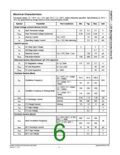
Electrical Characteristics
For typical values, TA = 25°C, VIN = 15V, and -25°C ≤ TA ≤ 85°C, unless otherwise specified. Specifications to -25°C ~
85°C are guaranteed by design based on final characterization results.
Symbol
Parameter
Test Conditions
Min.
Typ.
Max.
Unit
Under-Voltage Lockout Section (UVLO)
Vth
Vthhys
Ist
Start Threshold Voltage
Start Threshold Voltage Hysteresis
Start-up Current
4.9
5.2
0.45
70
5.5
0.60
100
3.5
V
V
0.20
VIN = 4.5V
µA
mA
Iop
Operating Supply Current
VIN = 15V, Not switching
2.0
ON/OFF Section
Von
Voff
On State Input Voltage
2
5
V
V
Off Stage Input Voltage
Stand-by Current
0.7
170
270
Isb
VIN = 15V, ENA = Low
120
200
µA
kΩ
RENA
Pull-down Resistor
130
4.9
Reference Section (Recommend 1µF X7R Capacitor)
V5
5V Regulation Voltage
5V Line Regulation
5V Load Regulation
5.0
5.1
50
50
V
0 ≤ I5 ≤ 3mA
6 ≤ VIN ≤ 24V
I5 = 3mA
V5line
V5load
mV
mV
Oscillator Section (Main)
TA = 25°C, CT = 220pF,
RT = 100kΩ
93.9
93
97.0
97
100.5
101
fosc
Oscillation Frequency
kHz
kHz
CT = 220pF, RT =
100kΩ
TA = 25°C, CT = 220pF,
RT = 100kΩ
120
119
124
124
129
fstr
Oscillator Frequency in Striking Mode
CT Discharge Current
CT = 220pF, RT =
100kΩ
129
Ictdcs
Ictdc
Ictcs
Vcth
Vctl
Striking
Normal
Striking
0.99
740
-15
1.14
840
-12
2
1.29
940
-9
mA
μA
μA
V
CT Charge Current
CT High Voltage
CT Low Voltage
0.4
V
Oscillator Section (Burst)
TA = 25°C, BCT = 4.7nF,
BRT = 1.4MΩ
303
314
314
326
foscb
Burst Oscillation Frequency
Hz
BCT = 4.7nF, BRT =
1.4MΩ
302
14
326
38
Ibctdc
Vbcth
Vbctl
BCT Discharge Current
BCT High Voltage
BCT Low Voltage
26
2
μA
V
0.5
V
© 2007 Fairchild Semiconductor Corporation
FAN7317 • 1.0.2
www.fairchildsemi.com
6

 FAIRCHILD [ FAIRCHILD SEMICONDUCTOR ]