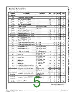
Electrical Characteristics
VDD=20V, TA=25°C, unless otherwise specified.
Symbol
Parameter
Conditions
Min.
Typ.
Max.
Units
SP/SN Section
Threshold Voltage of
VN-VP to Turn-Off SR MOS 1
Sweep VN-P- from LOW
to HIGH
VN-P(turn off) 1
VN-P(turn off) 2
VP-N(turn on) 1
VP-N(turn on) 2
3
3
3
3
4
4
4
4
5
5
5
5
5
V
V
Threshold Voltage of
VN-VP to Turn-Off SR MOS 2
Threshold Voltage of
VP-VN to Turn-On SR MOS 1
Sweep VP-N- from LOW
to HIGH
V
Threshold Voltage of
VP-VN to Turn-On SR MOS 2
Sweep VP-N- from LOW
to HIGH
V
Voltage Difference between
SP and SN
| VSP-VSN | /
Ratio_SP-SN
%
MIN(VSP,VSN
)
LPC Section
Connect a Diode
Charge Divide Discharge Current 1N4148 and Divider
Ratio_LPC-RES
2.79
3.00
3.21
Transfer Ratio vs. Input Voltage
(Ratio 12) to LPC,
DET = 3V, VLPC = 3V
V
VLPC-EN1
VLPC-EN2
LPC Enable Threshold Voltage 1
LPC Enable Threshold Voltage 2
1.8
1.8
2.0
2.0
2.2
2.2
V
V
VLPC-CLAMP1 Lower Clamp Voltage 1
VLPC-CLAMP2 Lower Clamp Voltage 2
ILPC-SOURCE1 Maximum Source Current 1
ILPC-SOURCE2 Maximum Source Current 2
ILPC = -5μA
ILPC = -5μA
VLPC = -0.3V
VLPC = -0.3V
0.10
0.10
0.25
0.25
250
250
0.40
0.40
300
300
V
V
μA
μA
Threshold Voltage for Disable
LPC Function
VLPC-LOW1
1.3
1.3
70
1.5
1.5
1.7
1.7
V
V
Threshold Voltage for Disable
LPC Function
VLPC-LOW2
Debounce Time for Disable LPC
μs
μs
tLPC-LOW1
Function
VLPC < VLPC-LOW
100
100
130
130
Debounce Time for Disable LPC
tLPC-LOW2
Function
VLPC < VLPC-LOW
70
© 2010 Fairchild Semiconductor Corporation
FAN6206 • Rev. 1.0.2
www.fairchildsemi.com
6

 FAIRCHILD [ FAIRCHILD SEMICONDUCTOR ]