XRT86L30
REV. 1.0.1
SINGLE T1/E1/J1 FRAMER/LIU COMBO
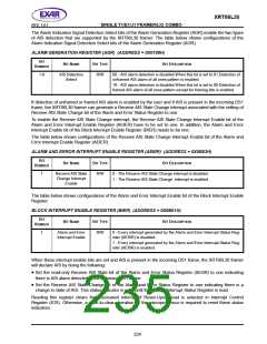
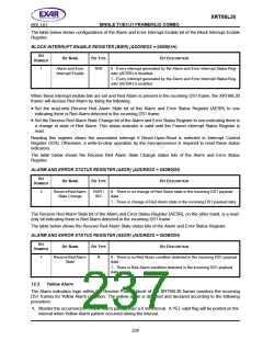
The table below shows configurations of the Alarm and Error Interrupt Enable bit of the Block Interrupt Enable
Register.
BLOCK INTERRUPT ENABLE REGISTER (BIER) (ADDRESS = 0X0B01H)
B
IT
B
IT
N
AME
B
IT
TYPE
BIT DESCRIPTION
N
UMBER
1
Alarm and Error
Interrupt Enable
R/W
0 - Every interrupt generated by the Alarm and Error Interrupt Status Reg-
ister (AEISR) is disabled.
1 - Every interrupt generated by the Alarm and Error Interrupt Status Reg-
ister (AEISR) is enabled.
When these interrupt enable bits are set and Red Alarm is present in the incoming DS1 frame, the XRT86L30
framer will declare Red Alarm by doing the following:
•
Set the read-only Receive Red Alarm State bit of the Alarm and Error Status Register (AESR) to one
indicating there is Red Alarm detected in the incoming DS1 frame.
•
Set the Receive Red Alarm State Change bit of the Alarm and Error Status Register to one indicating there is
a change in state of Red Alarm. This status indicator is valid until the Framer Interrupt Status Register is
read.
Reading this register clears the associated interrupt if Reset-Upon-Read is selected in Interrupt Control
Register (ICR). Otherwise, a write-to-clear operation by the microprocessor is required to reset these status
indicators.
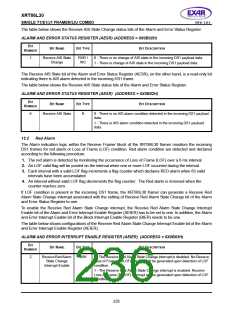
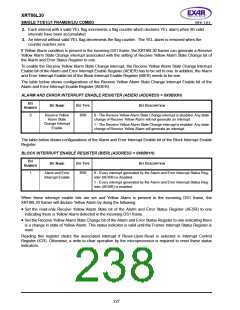
The table below shows the Receive Red Alarm State Change status bits of the Alarm and Error Status
Register.
ALARM AND ERROR STATUS REGISTER (AESR) (ADDRESS = 0X0B02H)
B
IT
B
IT
N
AME
B
IT
TYPE
BIT DESCRIPTION
N
UMBER
2
ReceiveRed Alarm
State Change
RUR /
WC
0 - There is no change of Red Alarm state in the incoming DS1 payload
data.
1 - There is change of Red Alarm state in the incoming DS1 payload data.
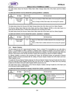
The Receive Red Alarm State bit of the Alarm and Error Status Register (AESR), on the other hand, is a read-
only bit indicating there is Red Alarm detected in the incoming DS1 frame.
The table below shows the Receive Red Alarm State status bits of the Alarm and Error Status Register.
ALARM AND ERROR STATUS REGISTER (AESR) (ADDRESS = 0X0B02H)
B
IT
B
IT
N
AME
B
IT
TYPE
BIT DESCRIPTION
N
UMBER
7
ReceiveRed Alarm
State
R
0 - There is no Red Alarm condition detected in the incoming DS1 payload
data.
1 - There is Red Alarm condition detected in the incoming DS1 payload
data.
12.3
Yellow Alarm
The Alarm indication logic within the Receive Framer block of the XRT86L30 framer monitors the incoming
DS1 frames for Yellow Alarm condition. The yellow alarm is detected and declared according to the following
procedure:
1. Monitor the occurrence of Yellow Alarm pattern over a 6 ms interval. A YEL valid flag will be posted on the
interval when Yellow Alarm pattern occurred during the interval.
226

 EXAR [ EXAR CORPORATION ]