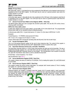
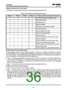
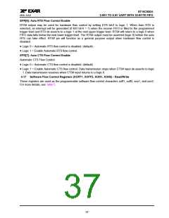
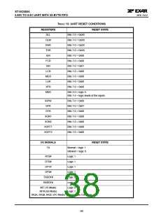
áç
ST16C650A
2.90V TO 5.5V UART WITH 32-BYTE FIFO
REV. 5.0.0
ABSOLUTE MAXIMUM RATINGS
Power Supply Range
7 Volts
Voltage at Any Pin
-0.5 to 7V
-40o to +85oC
Operating Temperature
-65o to +150oC
500 mW
Storage Temperature
Package Dissipation
theta-ja = 59oC/W, theta-jc = 16oC/W
Thermal Resistance (7x7x1.4mm 48-TQFP)
ELECTRICAL CHARACTERISTICS
DC ELECTRICAL CHARACTERISTICS
UNLESS OTHERWISE NOTED: TA=0O TO 70OC (-40O TO +85OC FOR INDUSTRIAL GRADE PACKAGE), VCC IS 2.90V TO
5.5V
LIMITS
3.3V
LIMITS
5.0V
SYMBOL
PARAMETER
UNITS
CONDITION
MIN
MAX MIN
MAX
VILCK
VIHCK
VIL
Clock Input Low Level
-0.3
2.4
0.6
VCC
0.8
-0.5
0.6
VCC
0.8
V
V
V
V
Clock Input High Level
Input Low Voltage
3.0
-0.5
2.0
-0.3
2.0
VIH
Input High Voltage
VCC
VCC
(top mark date code of "GC YYWW" and older)
VIH
Input High Voltage
2.0
5.5
0.4
2.0
5.5
0.4
V
(top mark date code of "HC YYWW" and newer)
VOL
VOL
VOH
VOH
IIL
Output Low Voltage
Output Low Voltage
Output High Voltage
Output High Voltage
Input Low Leakage Current
Input High Leakage Current
Input Pin Capacitance
Power Supply Current
Sleep Current
V
V
IOL = 5 mA
IOL = 4 mA
IOH = -5 mA
IOH = -1 mA
2.4
V
2.0
V
+/-10
+/-10
5
+/-10
+/-10
5
uA
uA
pF
mA
uA
IIH
CIN
ICC
1.3
3.0
ISLEEP
30
100
See Test1
Test 1: The following inputs should remain steady at VCC or GND state to minimize sleep current: A0-A2, D0-D7, IOR#,
IOW#, CS# and modem inputs. Also, RX input must idle at logic 1 state while in sleep mode. In mixed voltage
environments, where the voltage at any of the inputs of the 651 is lower than its VCC supply voltage, the sleep current will
be higher than the maximum values given here.
39

 EXAR [ EXAR CORPORATION ]