áç
ST16C650A
2.90V TO 5.5V UART WITH 32-BYTE FIFO
REV. 5.0.0
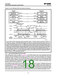
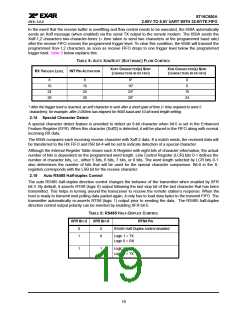
In the event that the receive buffer is overfilling and flow control needs to be executed, the 650A automatically
sends an Xoff message (when enabled) via the serial TX output to the remote modem. The 650A sends the
Xoff-1,2 characters two-character-times (= time taken to send two characters at the programmed baud rate)
after the receive FIFO crosses the programmed trigger level. To clear this condition, the 650A will transmit the
programmed Xon-1,2 characters as soon as receive FIFO drops to one trigger level below the programmed
trigger level. Table 5 below explains this:
TABLE 5: AUTO XON/XOFF (SOFTWARE) FLOW CONTROL
XOFF CHARACTER(S) SENT
(CHARACTERS IN RX FIFO)
XON CHARACTER(S) SENT
(CHARACTERS IN RX FIFO)
RX TRIGGER LEVEL
INT PIN ACTIVATION
8
8
8*
0
8
16
24
28
16
24
28
16*
24*
28*
16
24
* After the trigger level is reached, an xoff character is sent after a short span of time (= time required to send 2
characters); for example, after 2.083ms has elapsed for 9600 baud and 10-bit word length setting.
2.14 Special Character Detect
A special character detect feature is provided to detect an 8-bit character when bit-5 is set in the Enhanced
Feature Register (EFR). When this character (Xoff2) is detected, it will be placed in the FIFO along with normal
incoming RX data.
The 650A compares each incoming receive character with Xoff-2 data. If a match exists, the received data will
be transferred to the RX FIFO and ISR bit-4 will be set to indicate detection of a special character.
Although the Internal Register Table shows each X-Register with eight bits of character information, the actual
number of bits is dependent on the programmed word length. Line Control Register (LCR) bits 0-1 defines the
number of character bits, i.e., either 5 bits, 6 bits, 7 bits, or 8 bits. The word length selected by LCR bits 0-1
also determines the number of bits that will be used for the special character comparison. Bit-0 in the X-
registers corresponds with the LSB bit for the receive character.
2.15
Auto RS485 Half-duplex Control
The auto RS485 half-duplex direction control changes the behavior of the transmitter when enabled by XFR
bit-3. By default, it asserts RTS# (logic 0) output following the last stop bit of the last character that has been
transmitted. This helps in turning around the transceiver to receive the remote station’s response. When the
host is ready to transmit next polling data packet again, it only has to load data bytes to the transmit FIFO. The
transmitter automatically re-asserts RTS# (logic 1) output prior to sending the data. The RS485 half-duplex
direction control output polarity can be inverted by enabling XFR bit-5.
TABLE 6: RS485 HALF-DUPLEX CONTROL
XFR BIT-2
XFR BIT-5
RTS# PIN
0
1
X
0
RS485 Half-Duplex control disabled
Logic 1 = TX
Logic 0 = RX
1
1
Logic 1 = RX
Logic 0 = TX
19

 EXAR [ EXAR CORPORATION ]