ST16C650A
2.90V TO 5.5V UART WITH 32-BYTE FIFO
áç
REV. 5.0.0
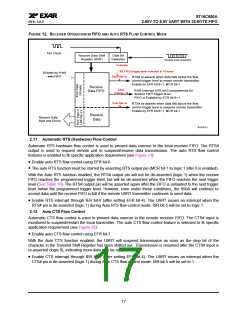
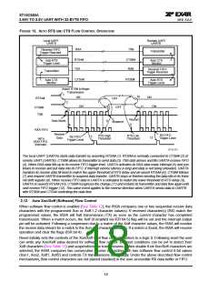
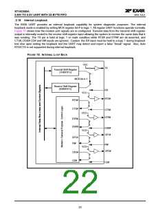
FIGURE 13. AUTO RTS AND CTS FLOW CONTROL OPERATION
Local UART
UARTA
Remote UART
UARTB
RXA
TXB
Receiver FIFO
Trigger Reached
Transmitter
RTSA#
TXA
CTSB#
RXB
Auto RTS
Auto CTS
Monitor
Trigger Level
Receiver FIFO
Trigger Reached
Transmitter
CTSA#
RTSB#
Auto CTS
Monitor
Auto RTS
Trigger Level
Assert RTS# to Begin
Transmission
1
10
ON
ON
ON
RTSA#
OFF
OFF
7
2
ON
11
CTSB#
TXB
8
3
Restart
Data Starts
6
Suspend
9
4
RXA FIFO
Receive
Data
RX FIFO
Trigger Level
RTS High
Threshold
RTS Low
Threshold
5
RX FIFO
Trigger Level
12
INTA
(RXA FIFO
Interrupt)
RTSCTS1
The local UART (UARTA) starts data transfer by asserting RTSA# (1). RTSA# is normally connected to CTSB# (2) of
remote UART (UARTB). CTSB# allows its transmitter to send data (3). TXB data arrives and fills UARTA receive FIFO
(4). When RXA data fills up to its receive FIFO trigger level, UARTA activates its RXA data ready interrupt (5) and con-
tinues to receive and put data into its FIFO. If interrupt service latency is long and data is not being unloaded, UARTA
monitors its receive data fill level to match the upper threshold of RTS delay and de-assert RTSA# (6). CTSB# follows
(7) and request UARTB transmitter to suspend data transfer. UARTB stops or finishes sending the data bits in its trans-
mit shift register (8). When receive FIFO data in UARTA is unloaded to match the lower threshold of RTS delay (9),
UARTA re-asserts RTSA# (10), CTSB# recognizes the change (11) and restarts its transmitter and data flow again until
next receive FIFO trigger (12). This same event applies to the reverse direction when UARTA sends data to UARTB
with RTSB# and CTSA# controlling the data flow.
2.13 Auto Xon/Xoff (Software) Flow Control
When software flow control is enabled (See Table 12), the 650A compares one or two sequential receive data
characters with the programmed Xon or Xoff-1,2 character value(s). If received character(s) (RX) match the
programmed values, the 650A will halt transmission (TX) as soon as the current character has completed
transmission. When a match occurs, the Xoff (if enabled via IER bit-5) flag will be set and the interrupt output
pin will be activated. Following a suspension due to a match of the Xoff character values, the 650A will monitor
the receive data stream for a match to the Xon-1,2 character value(s). If a match is found, the 650A will resume
operation and clear the flags (ISR bit-4).
Reset initially sets the contents of the Xon/Xoff 8-bit flow control registers to a logic 0. Following reset the user
can write any Xon/Xoff value desired for software flow control. Different conditions can be set to detect Xon/
Xoff characters (See Table 12) and suspend/resume transmissions. When double 8-bit Xon/Xoff characters are
selected, the 650A compares two consecutive receive characters with two software flow control 8-bit values
(Xon1, Xon2, Xoff1, Xoff2) and controls TX transmissions accordingly. Under the above described flow control
mechanisms, flow control characters are not placed (stacked) in the user accessible RX data buffer or FIFO.
18

 EXAR [ EXAR CORPORATION ]