áç
ST16C650A
2.90V TO 5.5V UART WITH 32-BYTE FIFO
REV. 5.0.0
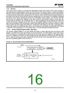
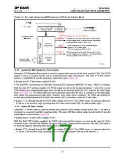
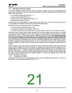
FIGURE 12. RECEIVER OPERATION IN FIFO AND AUTO RTS FLOW CONTROL MODE
16X Clock
Receive Data Shift
Register (RSR)
Data Bit
Validation
Receive Data Characters
Example
:
- RX FIFO trigger level selected at 16 bytes
32 bytes by 11-bit
wide FIFO
Data falls to
8
RTS# re-asserts when data falls below the flow
control trigger level to restart remote transmitter.
Enable by EFR bit-6=1, MCR bit-1.
Receive
Data FIFO
FIFO
Trigger=16
RHR Interrupt (ISR bit-2) programmed for
desired FIFO trigger level.
FIFO is Enabled by FCR bit-0=1
Data fills to
24
RTS# de-asserts when data fills above the flow
control trigger level to suspend remote transmitter.
Enable by EFR bit-6=1, MCR bit-1.
Receive
Data
Receive Data
Byte and Errors
RXFIFO1
2.11 Automatic RTS (Hardware) Flow Control
Automatic RTS hardware flow control is used to prevent data overrun to the local receiver FIFO. The RTS#
output is used to request remote unit to suspend/resume data transmission. The auto RTS flow control
features is enabled to fit specific application requirement (see Figure 13):
• Enable auto RTS flow control using EFR bit-6.
• The auto RTS function must be started by asserting RTS output pin (MCR bit-1 to logic 1 after it is enabled).
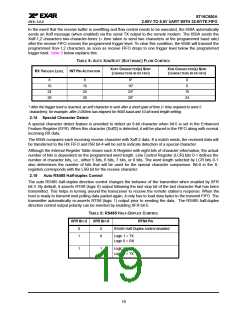
With the Auto RTS function enabled, the RTS# output pin will not be de-asserted (logic 1) when the receive
FIFO reaches the programmed trigger level, but will be de-asserted when the FIFO reaches the next trigger
level (See Table 10). The RTS# output pin will be asserted again after the FIFO is unloaded to the next trigger
level below the programmed trigger level. However, even under these conditions, the 650A will continue to
accept data until the receive FIFO is full if the remote UART transmitter continues to send data.
• Enable RTS interrupt through IER bit-6 (after setting EFR bit-4). The UART issues an interrupt when the
RTS# pin is de-asserted (logic 1) during Auto RTS flow control mode: ISR bit-5 will be set to logic 1.
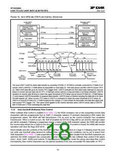
2.12 Auto CTS Flow Control
Automatic CTS flow control is used to prevent data overrun to the remote receiver FIFO. The CTS# input is
monitored to suspend/restart the local transmitter. The auto CTS flow control feature is selected to fit specific
application requirement (see Figure 13):
• Enable auto CTS flow control using EFR bit-7.
With the Auto CTS function enabled, the UART will suspend transmission as soon as the stop bit of the
character in the Transmit Shift Register has been shifted out. Transmission is resumed after the CTS# input is
re-asserted (logic 0), indicating more data may be sent.
• Enable CTS interrupt through IER bit-7 (after setting EFR bit-4). The UART issues an interrupt when the
CTS# pin is de-asserted (logic 1) during Auto CTS flow control mode: ISR bit-5 will be set to 1.
17

 EXAR [ EXAR CORPORATION ]