áç
ST16C650A
2.90V TO 5.5V UART WITH 32-BYTE FIFO
REV. 5.0.0
2.7
Crystal Oscillator or External Clock
The 650A includes an on-chip oscillator (XTAL1 and XTAL2). The crystal oscillator provides the system clock
to the Baud Rate Generators (BRG) in the UART. XTAL1 is the input to the oscillator or external clock buffer
input with XTAL2 pin being the output. Caution if external clock is used: XTAL1 input is not 5 Volt tolerant. For
programming details, see “Programmable Baud Rate Generator.”
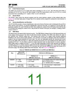
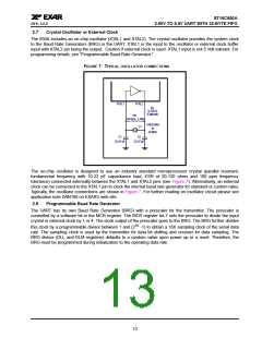
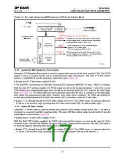
FIGURE 7. TYPICAL OSCILLATOR CONNECTIONS
XTAL1
XTAL2
R1
Ω
0-120
(Optional)
R2
500 ΚΩ − 1 ΜΩ
1.8432 MHz
to
Y1
24 MHz
C1
C2
22-47 pF
22-47 pF
The on-chip oscillator is designed to use an industry standard microprocessor crystal (parallel resonant,
fundamental frequency with 10-22 pF capacitance load, ESR of 20-120 ohms and 100 ppm frequency
tolerance) connected externally between the XTAL1 and XTAL2 pins (see Figure 7). Alternatively, an external
clock can be connected to the XTAL1 pin to clock the internal baud rate generator for standard or custom rates.
Typically, the oscillator connections are shown in Figure 7. For further reading on oscillator circuit please see
application note DAN108 on EXAR’s web site.
2.8
Programmable Baud Rate Generator
The UART has its own Baud Rate Generator (BRG) with a prescaler for the transmitter. The prescaler is
controlled by a software bit in the MCR register. The MCR register bit-7 sets the prescaler to divide the input
crystal or external clock by 1 or 4. The clock output of the prescaler goes to the BRG. The BRG further divides
this clock by a programmable divisor between 1 and (216 -1) to obtain a 16X sampling clock of the serial data
rate. The sampling clock is used by the transmitter for data bit shifting and receiver for data sampling. The
BRG divisor (DLL and DLM registers) defaults to a random value upon power up or a reset. Therefore, the
BRG must be programmed during initialization to the operating data rate.
13

 EXAR [ EXAR CORPORATION ]