áç
ST16C650A
2.90V TO 5.5V UART WITH 32-BYTE FIFO
REV. 5.0.0
2.2
5-Volt Tolerant Inputs
The 650A can acccept up to 5V inputs even when operating at 3.3V or 2.5V. But note that if the 650A is
operating at 2.5V, its VOH may not be high enough to meet the requirements of the VIH of a CPU or a serial
transceiver that is operating at 5V. Caution: XTAL1 is not 5 volt tolerant.
2.3
Device Reset
The RESET input resets the internal registers and the serial interface outputs to their default state (see
Figure 13). An active high pulse of longer than 40 ns duration will be required to activate the reset function in
the device.
2.4
Device Identification and Revision
The ST16C650A
provides a Device Identification code and a Device Revision code to distinguish the part from
other devices and revisions. To read the identification code from the part, it is required to set the baud rate
generator registers DLL and DLM both to 0x00. Now reading the content of the DLM will provide 0x04 for the
ST16C650A and reading the content of DLL will provide the revision of the part; for example, a reading of 0x01
means revision A.
2.5
DMA Mode
The device does not support direct memory access. The DMA Mode (a legacy term) in this document does not
mean “direct memory access” but refers to data block transfer operation. The DMA mode affects the state of
the RXRDY# and TXRDY# output pins. The transmit and receive FIFO trigger levels provide additional
flexibility to the user for block mode operation. The LSR bits 5-6 provide an indication when the transmitter is
empty or has an empty location(s) for more data. The user can optionally operate the transmit and receive
FIFO in the DMA mode (FCR bit-3=1). When the transmit and receive FIFO are enabled and the DMA mode is
disabled (FCR bit-3 = 0), the 650A is placed in single-character mode for data transmit or receive operation.
When DMA mode is enabled (FCR bit-3 = 1), the user takes advantage of block mode operation by loading or
unloading the FIFO in a block sequence determined by the programmed trigger level. In this mode, the 650A
sets the TXRDY# pin when the transmit FIFO becomes full, and sets the RXRDY# pin when the receive FIFO
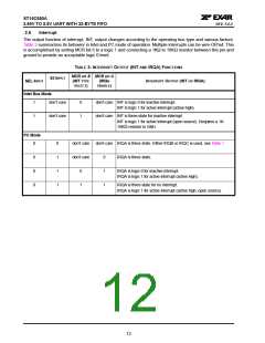
becomes empty. The following table shows their behavior. Also see Figures 24 through 29.
ABLE
T
AND
UTPUTS IN
RXRDY# O
AND
ODE
DMA M
2: TXRDY#
FIFO
FCR BIT-0=0
PINS
FCR BIT-0=1 (FIFO ENABLED)
(FIFO DISABLED)
FCR BIT-3 = 0
FCR BIT-3 = 1
(DMA MODE DISABLED)
(DMA MODE ENABLED)
RXRDY#
TXRDY#
0 = 1 byte.
0 = at least 1 byte in FIFO
1 = FIFO empty.
1 to 0 transition when FIFO reaches the trigger
level, or timeout occurs.
1 = no data.
0 to 1 transition when FIFO empties.
0 = THR empty.
1 = byte in THR.
0 = FIFO empty.
0 = FIFO has at least 1 empty location.
1 = FIFO is full.
1 = at least 1 byte in FIFO.
11

 EXAR [ EXAR CORPORATION ]