ST16C650A
2.90V TO 5.5V UART WITH 32-BYTE FIFO
áç
REV. 5.0.0
2.6
Interrupt
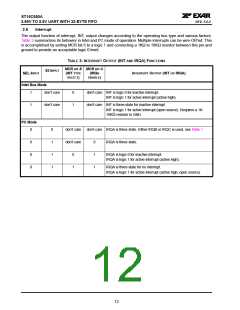
The output function of interrupt, INT, output changes according to the operating bus type and various factors.
Table 3 summarizes its behavior in Intel and PC mode of operation. Multiple interrupts can be wire-OR’ed. This
is accomplished by setting MCR bit-5 to a logic 1 and connecting a 1KΩ to 10KΩ resistor between this pin and
ground to provide an acceptable logic 0 level.
TABLE 3: INTERRUPT OUTPUT (INT AND IRQA) FUNCTIONS
MCR BIT-5 MCR BIT-3
S3 INPUT
SEL INPUT
(INT TYPE
SELECT)
(IRQN
INTERRUPT OUTPUT (INT OR IRQA)
ENABLE)
Intel Bus Mode
1
don’t care
0
1
don’t care INT is logic 0 for inactive interrupt.
INT is logic 1 for active interrupt (active high)
1
don’t care
don’t care INT is three-state for inactive interrupt
INT is logic 1 for active interrupt (open source). Requires a 1K-
10KΩ resistor to GND.
PC Mode
0
0
1
1
1
don’t care
don’t care IRQA is three-state. Either IRQB or IRQC is used, see Table 1.
0
0
0
don’t care
0
1
1
IRQA is three-state.
0
1
IRQA is logic 0 for inactive interrupt.
IRQA is logic 1 for active interrupt (active high).
IRQA is three-state for no interrupt.
IRQA is logic 1 for active interrupt (active high, open source).
12

 EXAR [ EXAR CORPORATION ]