Hardware
Design notes
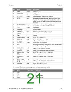
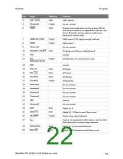
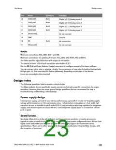
Pin
Name
Direction
Function
30
31
32
33
34
35
36
37
DIO3/AD3
Both
Digital I/O 3 / Analog input 3
Digital I/O 2 / Analog input 2
Digital I/O 1 / Analog input 1
Digital I/O 0 / Analog input 0
Do not connect
DIO2/AD2
DIO1/AD1
DIO0/AD0
[Reserved]
GND
Both
Both
Both
-
-
Ground
RF
Both
-
RF connection
[Reserved]
Do not connect
Notes
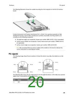
Minimum connections: VCC, GND, DOUT and DIN.
Minimum connections for updating firmware: VCC, GND, DIN, DOUT, RTS and DTR.
The table specifies signal direction with respect to the device.
The device includes a 50 kΩ pull-up resistor attached to RESET.
Use the PR (Pull-up/Down Resistor Enable) command to configure several of the input pull-ups.
You can connect other pins to external circuitry for convenience of operation including the Associate
LED pin (pin 15). The Associate LED flashes differently depending on the state of the device.
Leave any unused pins disconnected.
Design notes
The following guidelines help to ensure a robust design.
The XBee modules do not specifically require any external circuitry specific connections for proper
operation. However, there are some general design guidelines that we recommend for help in
troubleshooting and building a robust design.
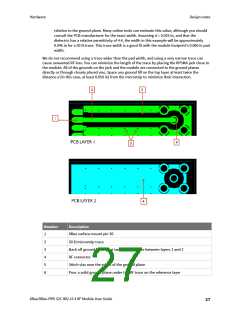
Power supply design
A poor power supply can lead to poor device performance, especially if you do not keep the supply
voltage within tolerance or if it is excessively noisy. To help reduce noise, place a 1.0 μF and 8.2 pF
capacitor as near as possible to pin 1 on the PCB. If you are using a switching regulator for the power
supply, switch the frequencies above 500 kHz. Limit the power supply ripple to a maximum 100 mV
peak to peak.
Board layout
We design XBee devices to be self sufficient and have minimal sensitivity to nearby processors,
crystals or other printed circuit board (PCB) components. Keep power and ground traces thicker than
signal traces and make sure that they are able to comfortably support the maximum current
specifications. There are no other special PCB design considerations to integrate XBee devices, with
the exception of antennas.
XBee/XBee-PRO S2C 802.15.4 RF Module User Guide
23

 ETC [ ETC ]