Hardware
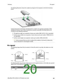
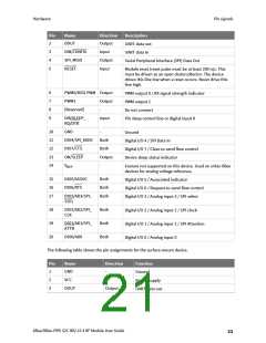
Pin signals
Pin
Name
Direction
Description
2
3
4
5
DOUT
Output
UART data out
DIN/CONFIG
SPI_MISO
RESET
Input
UART data In
Output
Input
Serial Peripheral Interface (SPI) Data Out
Module reset (reset pulse must be at least 200 ns). This
must be driven as an open drain/collector. The device
drives this line low when a reset occurs. Never drive this
line high.
6
7
8
9
PWM0/RSSI PWM Output
PWM output 0 / RX signal strength indicator
PWM output 1
PWM1
Output
-
[Reserved]
Do not connect
DI8/SLEEP_
RQ/DTR
Input
Pin sleep control line or digital input 8
10
11
12
13
14
GND
-
Ground
DIO4/SPI_MOSI
DIO7/CTS
ON/SLEEP
Both
Both
Output
-
Digital I/O 4 / SPI Data In
Digital I/O 7 / Clear-to-send flow control
Device sleep status indicator
V
Feature not supported on this device. Used on other XBee
devices for analog voltage reference.
REF
15
16
17
DIO5/ASSOC
DIO6/RTS
Both
Both
Both
Digital I/O 5 / Associated indicator
Digital I/O 6 / Request-to-send flow control
Digital I/O 3 / Analog input 3 / SPI select
DIO3/AD3/SPI_
SSEL
18
19
20
DIO2/AD2/SPI_
CLK
Both
Both
Both
Digital I/O 2 / Analog input 2 / SPI clock
Digital I/O 1 / Analog input 1 / SPI Attention
Digital I/O 0 / Analog input 0
DIO1/AD1/SPI_
ATTN
DIO0/AD0
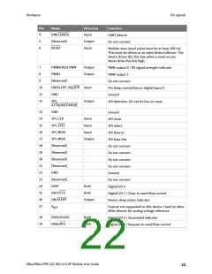
The following table shows the pin assignments for the surface-mount device.
Pin
Name
Direction
Function
1
GND
-
Ground
2
3
VCC
-
Power supply
UART data out
DOUT
Output
XBee/XBee-PRO S2C 802.15.4 RF Module User Guide
21

 ETC [ ETC ]