Page 20
Epson Research and Development
Vancouver Design Center
4.3.2 Buffered LCD Connector
J1 provides the same LCD panel signals as those directly from S1D13506, but with
voltage-adapting buffers which can be set to 3.3V or 5V. Pin 32 on this connector provides
power for the LCD panel logic at the same voltage as the buffer power supply.
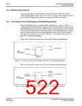
4.3.3 16-bit Passive Color Panel Support with MediaPlug Enabled
When the MediaPlug option is enabled, (MD13 and MD14 set to “On”, see Table 3-1:,
“Configuration DIP Switch Settings” on page 9) S1D13506 pins FPDAT[15:8] are used for
the MediaPlug interface and are not available for panel connection. Instead, S1D13506 pins
FPDAT[7:0] are multiplexed for 16-bit panel operation. If the MediaPlug option is selected
and 16-bit panel operation is desired, demultiplexing circuitry must be built externally
according to the schematic below. Refer to Table 4-7:, “LCD Signal Connector (J1)” on
page 18 for connector pin mapping.
Single color 16-bit passive panels can be used with the following modifications.
D[7:0]
To 16-bit panel
FPDAT[7:0]
D[15:8]
Q
D
FROM
S5U13506B00C
FPSHIFT
CK
74AHC374
Figure 4-1: External Circuit for Color Single 16-Bit Panel with MediaPlug Enabled
Dual color 16-bit passive panels can be used with the following modifications.
UD [3:0]
LD [3:0]
To 16-bit panel
FPDAT[7:4]
FPDAT[3:0]
UD [7:4]
LD [7:4]
Q
D
FROM
S5U13506B00C
FPSHIFT
CK
74AHC374
Figure 4-2: External Circuit for Color Dual 16-Bit Panel with MediaPlug Enabled
S1D13506
X25B-G-004-06
S5U13506B00C Evaluation Board User Manual
Issue Date: 01/02/06

 EPSON [ EPSON COMPANY ]