Epson Research and Development
Page 21
Vancouver Design Center
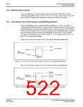
4.3.4 Adjustable LCD Panel Positive Power Supply
For LCD panels which require a positive bias voltage between +24V and +40V
(Iout=45mA), a power supply has been provided as an integral part of the S5U13506B00C
design. The voltage on VDDH can be adjusted using R15 to provide an output voltage from
+24V to +40V and can be enabled and disabled by LCDPWR (S1D13506 pin 75).
The S5U13506B00C was designed using LCDPWR (pin 75) to control the LCD bias
power. This design is no longer supported. Applications should use one of the available
GPIO pins to control the LCD bias power allowing for software control of power
sequencing delays. For further information on LCD power sequencing, see the S1D13506
Programming Notes and Examples, document number X25B-G-003-xx.
Note
Before connecting the panel, set the potentiometer according to the panel’s specific
voltage requirements.
4.3.5 Adjustable LCD Panel Negative Power Supply
For LCD panels which require a negative bias voltage between -23V and -14V
(Iout=25mA), a power supply has been provided as an integral part of the S5U13506B00C
design. The voltage on VLCD can be adjusted using R21 to provide an output voltage from
-23V to -14V, and can be enabled and disabled by LCDPWR (S1D13506 pin 75).
The S5U13506B00C was designed using LCDPWR (pin 75) to control the LCD bias
power. This design is no longer supported. Applications should use one of the available
GPIO pins to control the LCD bias power allowing for software control of power
sequencing delays. For further information on LCD power sequencing, see the S1D13506
Programming Notes and Examples, document number X25B-G-003-xx.
Note
Before connecting the panel, set the potentiometer according to the panel’s specific
voltage requirements.
S5U13506B00C Evaluation Board User Manual
Issue Date: 01/02/06
S1D13506
X25B-G-004-06

 EPSON [ EPSON COMPANY ]