Epson Research and Development
Page 161
Vancouver Design Center
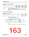
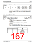
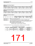
CRT/TV Ink/Cursor FIFO High Threshold Register
REG[08Eh]
RW
CRT/TV
Ink/Cursor
FIFO High
Threshold
Bit 3
CRT/TV
Ink/Cursor
FIFO High
Threshold
Bit 2
CRT/TV
Ink/Cursor
FIFO High
Threshold
Bit 1
CRT/TV
Ink/Cursor
FIFO High
Threshold
Bit 0
n/a
n/a
n/a
n/a
bits 5-0
CRT/TV Ink/Cursor FIFO High Threshold Bits [5:0]
These bits are used to optimize the display memory request arbitration for the Hardware
Cursor/Ink Layer. When this register is set to 00h, the threshold is automatically set in
hardware.
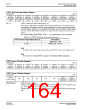
8.3.12 BitBlt Configuration Registers
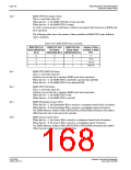
BitBlt Control Register 0
REG[100h]
RW
BitBlt FIFO
Not Empty
Status (RO)
BitBlt FIFO
Half Full
Status (RO)
BitBlt FIFO
Full
Status (RO)
BitBlt
Destination
Linear Select
BitBlt Active
Status
BitBlt Source
Linear Select
n/a
n/a
bits 7
BitBlt Active Status
This register bit has two data paths, one for write, the other for read.
Write Data Path
When software writes a one to this bit, it will initiate the 2D operation.
Read Data Path
The read back of this register indicates the status of the 2D engine.
When a read from this bit = 1, the 2D engine is busy.
When a read from this bit = 0, the 2D engine is idle and is ready for the next operation.
.
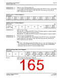
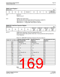
Table 8-29: BitBlt Active Status
BitBlt Active Status
State
Write
Read
0
0
1
1
0
1
0
1
Idle
Reserved
Initiating operation
Operation in progress
Hardware Functional Specification
Issue Date: 01/02/06
S1D13506
X25B-A-001-10

 EPSON [ EPSON COMPANY ]