Page 154
Epson Research and Development
Vancouver Design Center
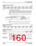
LCD Ink/Cursor Start Address Register
REG[071h]
RW
LCD
LCD
LCD
LCD
LCD
LCD
LCD
LCD
Ink/Cursor
Ink/Cursor
Ink/Cursor
Ink/Cursor
Ink/Cursor
Ink/Cursor
Ink/Cursor
Ink/Cursor
Start Address Start Address Start Address Start Address Start Address Start Address Start Address Start Address
Bit 7 Bit 6 Bit 5 Bit 4 Bit 3 Bit 2 Bit 1 Bit 0
bits 7-0
LCD Ink/Cursor Start Address Bits [7:0]
Encoded bits defining the start address for the LCD Ink/Cursor. For Cursor modes, a start
address of 0 should be valid for most applications. For Ink or special Cursor modes, the
start address should be set at an address location that does not conflict with the display
memory of Dual Panel Buffer, which always takes the top M memory locations in bytes,
where
M = (Panel Height x Panel Width / 16) x c, c = 1 for monochrome, 4 for color panel.
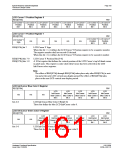
Table 8-26: LCD Ink/Cursor Start Address Encoding
LCD Ink/Cursor Start Address Bits [7:0]
Start Address
Memory Size - 1024
Memory Size - n x 8192
0
n = 255...1
Note
The effect of this register takes place at the next LCD vertical non-display period.
Note
See Section 10, “Display Buffer” on page 182 for display buffer organization.
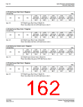
LCD Cursor X Position Register 0
REG[072h]
RW
LCD Cursor X LCD Cursor X LCD Cursor X LCD Cursor X LCD Cursor X LCD Cursor X LCD Cursor X LCD Cursor X
Position
Bit 7
Position
Bit 6
Position
Bit 5
Position
Bit 4
Position
Bit 3
Position
Bit 2
Position
Bit 1
Position
Bit 0
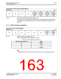
LCD Cursor X Position Register 1
REG[073h]
RW
LCD Cursor X LCD Cursor X
LCD Cursor X
n/a
n/a
n/a
n/a
n/a
Position
Bit 9
Position
Bit 8
Sign
REG[073h] bit 7
LCD Cursor X Sign
When this bit = 1, it defines the LCD Cursor X Position register to be a negative number.
The negative number shall not exceed 63 decimal.
When this bit = 0, it defines the LCD Cursor X Position register to be a positive number.
REG[072h] bits 7-0
REG[073h] bits 1-0
LCD Cursor X Position Bits [9:0]
A 10-bit register that defines the horizontal position of the LCD Cursor’s top left hand
corner in pixel units. This register is only valid when Cursor has been selected in the LCD
Ink/Cursor select registers.
S1D13506
X25B-A-001-10
Hardware Functional Specification
Issue Date: 01/02/06

 EPSON [ EPSON COMPANY ]