Page 144
Epson Research and Development
Vancouver Design Center
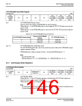
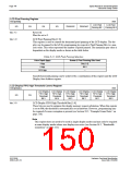
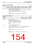
LCD Pixel Panning Register
REG[048h]
RW
LCD Pixel
Panning Bit 1 Panning Bit 0
LCD Pixel
n/a
n/a
n/a
n/a
Reserved
Reserved
bits 3-2
bits 1-0
Reserved.
Must be set to 0.
LCD Pixel Panning Bits [1:0]
This register is used to control the horizontal pixel panning of the LCD display. The dis-
play can be panned to the left by programming its respective Pixel Panning Bits to a non-
zero value. This value represents the number of pixels panned. The maximum pan value is
dependent on the display mode as shown in the table below.
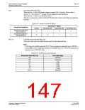
Table 8-21: LCD Pixel Panning Selection
Color Depth (bpp)
4 bpp
Screen 2 Pixel Panning Bits Used
Bits [1:0]
Bit 0
8 bpp
15/16 bpp
---
Smooth horizontal panning can be achieved by a combination of this register and the LCD
Display Start Address register.
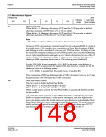
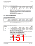
LCD Display FIFO High Threshold Control Register
REG[04Ah]
RW
LCD Display LCD Display LCD Display LCD Display LCD Display LCD Display
FIFO High
Threshold
Bit 5
FIFO High
Threshold
Bit 4
FIFO High
Threshold
Bit 3
FIFO High
Threshold
Bit 2
FIFO High
Threshold
Bit 1
FIFO High
Threshold
Bit 0
n/a
n/a
bits 5-0
LCD Display FIFO High Threshold Bits [5:0]
These bits are used to optimize the display memory request arbitration. When this register
is set to 00h, the threshold is automatically set in hardware. However, programming may
be required if screen corruption is present (see Section 18.2, “Example Frame Rates” on
page 216).
Note
This register does not need to be used in single display modes and may only be required
in some display modes where two displays are active (see Section 16.2, “Bandwidth
Limitation” on page 211).
S1D13506
X25B-A-001-10
Hardware Functional Specification
Issue Date: 01/02/06

 EPSON [ EPSON COMPANY ]