EM6603
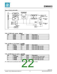
11 Serial (Output) Write Buffer – SWB
The EM6603 has a simple Serial Write Buffer (SWB) which outputs serial data and serial clock.
The SWB is enabled by setting the bit V03 in the CLKSWB register as well as setting port D to output mode.
The combination of the possible PortD mode is shown in Table 34. In SWB mode the serial clock is output on
port D0 and the serial data is output on port D1.
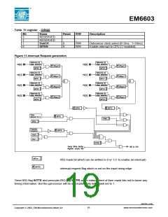
The signal TestVar[3], which is used by the processor to make conditional jumps, indicates "Transmission
finished" in automatic send mode or "SWBbuffer empty" in interactive send mode. In interactive mode,
TestVar[3] is equivalent to the interrupt request flags stored in IntRq register : it permits to recognize the
interrupt source. (See also the interrupt handling section 9.Interrupt Controller for further information). To serve
the "SWBbuffer empty " interrupt request, one only has to make a conditional jump on TestVar[3].
Table 34.SWB clock selection
The Serial Write Buffer output clock frequency is
SWB clock output
CkSWB1
CkSWB0
selected by bits ClkSWB0 and ClkSWB1 in the
ClkSWB register. The possible values are 1kHz
(default), 2kHz, 8kHz or 16kHz and are shown in
Table 34.
1024 Hz
0
0
1
1
0
1
0
1
2048 Hz
8192 Hz
16384 Hz
Table 35.SWB clock selection register - ClkSWB
Bit
Name
Reset
R/W
R/W
R
Description
3
V03
0
0
0
0
Serial Write buffer selection
RESERVED - read 0
SWB clock selector 1
SWB clock selector 0
2
-
1
CkSWB1
CkSWB0
R/W
R/W
0
Table 36.PortD status
PortD status CIOPD V03
PD0
input
PD1
PD2
PD3
input
input
« NORMAL »
« NORMAL »
« NORMAL »
« SWB »
0
0
1
1
0
1
0
1
input
input
input
input
input
output PD0
output PD1
SWB serial data
output PD2
output PD2
output PD3
output PD3
serial clock Out
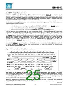
When the SWB is enabled by setting the bit V03 TestVar[3], which is used to make conditional jumps, is
reassigned to the SWB and indicates either "SWBbuffer empty " interrupt or "Transmission finished" . After
Power-on-RESET V03 is cleared at "0" and TestVar[3] is consequently assigned to PA2 input terminal.
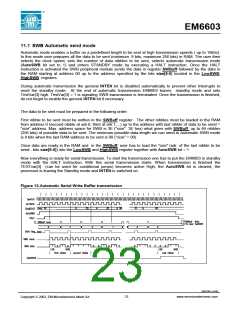
The SWB data is output on the rising edge of the clock. Consequently, on the receiver side the serial data can
be evaluated on falling edge of the serial clock edge.
03/02 REV. G/439
21
www.emmicroelectronic.com
Copyright 2002, EM Microelectronic-Marin SA

 EMMICRO [ EM MICROELECTRONIC - MARIN SA ]