EM78P341N/342N/343N
8-Bit Microprocessor with OTP ROM
Bit 2 (LVDEN): Low Voltage Detector Enable bit
0 = Low voltage detector disable
1 = Low voltage detector enable
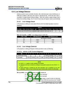
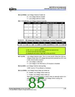
Bits 1~0 (LVD1:0): Low Voltage Detector level bits.
LVDEN
LVD1, LVD0
LVD voltage Interrupt Level
/LVD
Vdd ≤ 2.3V
Vdd > 2.3V
Vdd ≤ 3.3V
Vdd > 3.3V
Vdd ≤ 4.0V
Vdd > 4.0V
Vdd ≤ 4.5V
Vdd > 4.5V
NA
0
1
0
1
0
1
0
1
0
1
11
1
1
10
01
1
0
00
××
6.14.2.2 RE (Interrupt Status 2 & Wake-up Control Register)
Bit 7
Bit 6
Bit 5
Bit 4
Bit 3
Bit 2
Bit 1
Bit 0
/LVD
LVDIF
ADIF
CMPIF
ADWE
CMPWE
ICWE
LVDWE
NOTE
■ RE < 6, 5, 4 > can be cleared by instruction but cannot be set.
■ IOCE0 is the interrupt mask register.
■ Reading RE will result to "logic AND" of RE and IOCE0.
Bit 7 (/LVD): Low voltage Detector state. This is a read only bit. When the VDD pin
voltage is lower than LVD voltage interrupt level (selected by LVD1 and
LVD0), this bit will be cleared.
0 = Low voltage is detected.
1 = Low voltage is not detected or LVD function is disabled.
Bit 6 (LVDIF): Low Voltage Detector interrupt flag
LVDIF reset to “0” by software or hardware.
Bit 0 (LVDWE): Low Voltage Detect wake-up enable bit.
0 = Disable Low Voltage Detect wake-up.
1 = Enable Low Voltage Detect wake-up.
When the Low Voltage Detect is used to enter an interrupt vector or to
wake up the IC from sleep with Low Voltage Detect running, the
LVDWE bit must be set to “Enable“.
Product Specification (V1.0) 12.01.2006
(This specification is subject to change without further notice)
• 79

 ELAN [ ELAN MICROELECTRONICS CORP ]