EM78P341N/342N/343N
8-Bit Microprocessor with OTP ROM
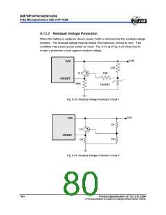
6.14 Low Voltage Detector
During a power source unstable situation, like external power noise interference or
EMS test condition, will cause the power to vibrate fiercely. At the time the Vdd is
unsettled, it maybe below working voltage. When the system supply voltage Vdd is
below the working voltage, the IC kernel must keep all register status automatically.
6.14.1 Low Voltage Reset
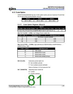
LVR property is setting at code option Word 0, Bit 10,9 detail operation mode as
following :
Word 0
Bit 12 Bit 11 Bit 10 Bit 9 Bit 8
Bit 7
Bit 6 Bit 5 Bit 4 Bit 3 Bit 2 Bit 1 Bit 0
LVR1 LVR0 TYPE1 TYPE0 CLKS ENWDTB OSC2 OSC1 OSC0 HLP
−
−
−
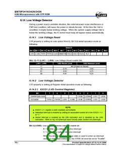
Bits 12~11 (LVR1 ~ LVR0): Low Voltage Reset enable bits.
LVR1, LVR0
VDD Reset Level
VDD Release Level
11
10
01
00
NA (Power-on Reset)
2.7V
3.5V
4.0V
2.9V
3.7V
4.2V
6.14.2 Low Voltage Detector
LVD property is setting at Register detail operation mode as following:
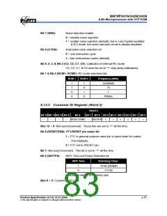
6.14.2.1 IOCD1 (LVD Control Register)
Bit
7
6
5
4
3
2
1
0
LVDEN
LVDEN
EM78P342L/343L
ICE342N
-
-
-
-
LVDIE
LVD1
LVD1
LVD0
LVD0
TYPE1 TYPE0 LVR1
LVR0 LVDIE
NOTE
■ IOCD1< 3 > register is both readable and writable
■ Individual interrupt is enabled by setting its associated control bit in the IOCD1< 4 >
to "1."
■ Global interrupt is enabled by the ENI instruction and is disabled by the DISI
instruction. Refer to Fig. 6-8 (Interrupt Input Circuit) under Section 6.6 (Interrupt).
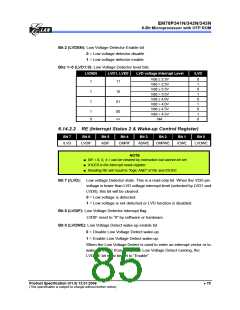
Bit 3 (LVDIE): Low voltage Detector interrupt enable bit.
0 = Disable Low voltage Detector interrupt
1 = Enable Low voltage Detector interrupt
When the detect low level voltage state is used to enter an interrupt
vector or enter next instruction, the LVDIE bit must be set to “Enable“.
78 •
Product Specification (V1.0) 12.01.2006
(This specification is subject to change without further notice)

 ELAN [ ELAN MICROELECTRONICS CORP ]