Package Power Dissipation
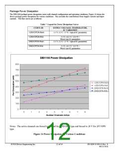
The DEI1184 package power dissipation varies with channel configuration and operating conditions. Figure 14 shows the
device package power dissipation for various conditions. This includes the contributions from Supply currents and Input
currents. The four curves are as follows:
Table 7 Legend for Power Dissipation Curves
CURVE ID
+28V/OPEN-Nom
+28V/OPEN-Wst
GND/OPEN-Nom
GND/OPEN-Wst
SUPPLY VOLTAGE, TEMPERATURE,
IC VARIATION
3.3 V, 12 V / 27 ºC / typical IC parameters
3.3 V, 16.5 V / 125 ºC /
Worst case IC parameters
3.3 V, 12 V / 27 ºC / typical IC parameters
3.3 V, 16.5 V / 125 ºC /
Worst case IC parameters
Notes: The active channels are forced to Ground for GND/OPN type and forced to 28 V for 28V/OPN
type.
Figure 14 Power Dissipation for Various Conditions
©2018 Device Engineering Inc.
12 of 14
DS-MW-01184-01 Rev. E
06/25/2018

 DEIAZ [ Device Engineering Incorporated ]