2. The transmitter FIFO can store 32 words
maximum and ignores attempts to load additional
data if full.
SELF TEST
If control register bit CR5 is set low, the transmitter serial
output data are internally connected to each of the two
receivers, bypassing the analog interface circuitry. Data is
passed unmodified to receiver 1 and inverted to receiver 2.
The serial data from the transmitter is always present on
the 429DO and /429DO outputs regardless of the state of
CR5.
REPEATER OPERATION
Repeater mode of operation allows a data word that has
been received by the device to be placed directly into the
transmitter FIFO. Repeater operation is similar to normal
receiver operation. In normal operation, either byte of a
received data word may be read from the receiver latches
SYSTEM OPERATION
The two receivers are independent of the transmitter.
Therefore, control of data exchanges is strictly at the
option of the user. The only restrictions are:
first by use of SEL input.
During repeater operation
however, the lower byte of the data word must be read
first. This is necessary because, as the data is being read, it
is also being loaded into transmitter FIFO which is always
loaded with the lower byte of data word first. Signal flow
for repeater operation is shown in the timing diagram
section.
1. The receive data will be overwritten if the
receiver FIFO is full and at least one location is
not retrieved before the next complete ARINC
word is received.
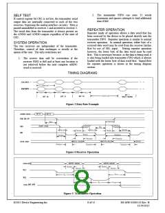
TIMING DIAGRAMS
Figure 3 Data Rate Example
Figure 4 Receiver Operation
Figure 5 Transmitter Operation
©2015 Device Engineering Inc.
8 of 15
DS-MW-01084-02 Rev. H
11/24/2015

 DEIAZ [ Device Engineering Incorporated ]