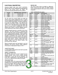
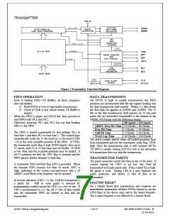
TRANSMITTER
Figure 2 Transmitter Function Diagram
FIFO OPERATION
DATA TRANSMISSION
Prior to loading FIFO (TX Buffer), do these (sequence
does not matter):
Set ENTX to high to enable transmission, the FIFO
positions are incremented with the top register loading into
the data transmission shift register. Within 2.5 data clocks
the first data bit appears at 429DO and /429DO. The 32
bits in the data transmission shift register (or 31 bits plus
parity bit) are presented sequentially to the outputs in the
ARINC 429 format with the following timing:
HI Speed LO Speed
1) Hold ENTX at Low to stop enable transmission
2) Check if TX/R is low (which means TX Buffer is
empty).
When the FIFO is empty and ENTX low, then proceed to
load FIFO with /PL1 and /PL2.
Otherwise asserting /PL1 and /PL2 has not data loading
effect to the FIFO.
10 Clocks 80 Clocks
5 Clocks
5 Clocks
ARINC Data Bit Time
Data Bit Time
Null Bit Time
40 Clocks
40 Clocks
The FIFO is loaded sequentially by first pulsing /PL1 to
load byte 1 and then /PL2 to load byte 2. The control logic
automatically loads the 31 bit word (or 32 bit word if CR4
= 0) in the next available position of the FIFO. If TX/R,
the transmitter ready flag is high (FIFO empty), then up to
32 words, each 31 or 32 bits long, may be loaded. If TX/R
is low, then only the available positions may be loaded. If
all 32 positions are full, the /FFT flag is asserted and the
FIFO ignores further attempts to load data.
40 Clocks 320 Clocks
Word Gap Time
The word counter detects when all loaded positions have
been transmitted and sets the transmitter ready flag, TX/R,
high. Once the transmission start it will continue till the
TX FIFO is empty. Setting ENTX to low at the mid point
of transmission does not stop the transmission.
TRANSMITTER PARITY
The parity generator counts the Ones in the 31 bit word. If
control register bit CR12 is set low, the 32nd bit
transmitted will make parity odd. If the control bit is high,
the parity is even. Setting CR4 to a zero bypasses the
parity generator, and allows 32 bits of data to be
transmitted.
A transmitter FIFO half-full flag /HFT is provided. When
the transmit FIFO contains less than 16 words, /HFT is
high, indicating to the system microprocessor that a 16
ARINC word block write sequence can be initiated.
In normal operation (CR4 = 1), the 32nd bit transmitted is
MASTER RESET
a parity bit.
Odd or even parity is selected by
On a Master Reset data transmission and reception are
immediately terminated, all three FIFOs cleared as are the
FIFO flags at the device pins and in the Status Register.
The Control Register is not affected by a Master Reset.
programming control register bit CR12 to a zero or one. If
CR4 is programmed to a 0, the all 32 bits of data loaded
into the transmitter FIFO are treated as data and are
transmitted.
©2015 Device Engineering Inc.
7 of 15
DS-MW-01084-02 Rev. H
11/24/2015

 DEIAZ [ Device Engineering Incorporated ]