DS1050/DS1052
The DS1050/DS1052 may operate in the following two modes:
1. Slave receiver mode: Serial data and clock are received through SDA and SCL, respectively. After
each byte is received, an acknowledge bit is transmitted. START and STOP conditions are
recognized as the beginning and end of a serial transfer. Address recognition is performed by
hardware after reception of the slave (device) address and direction bit.
2. Slave transmitter mode: The first byte is received and handled as in the slave receiver mode.
However, in this mode the direction bit will indicate that the transfer direction is reversed. Serial data
is transmitted on SDA by the DS1050/DS1052 while the serial clock is input on SCL. START and
STOP conditions are recognized as the beginning and end of a serial transfer.
SLAVE ADDRESS
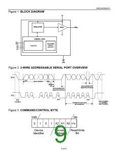
A command/control byte is the first byte received following the START condition from the master
device. The command/control byte consists of a four bit control code. For the DS1050/DS1052, this is
set as 0101 binary for read/write operations. The next three bits of the command/control byte are the
device select bits or slave address (A2, A1, A0). They are used by the master device to select which of
eight possible devices is to be accessed. When reading or writing the DS1050/DS1052, the device select
bits must match the device select pins (A2,A1,A0). The last bit of the command/control byte (R/W)
defines the operation to be performed. When set to a one a read operation is selected, and when set to a
zero a write operation is selected. The command control byte is presented in Figure 3.
Following the START condition, the DS1050/DS1052 monitors the SDA bus checking the device type
identifier being transmitted. Upon receiving the 0101 control code, the appropriate device address bits,
and the read/write bit, the slave device outputs an “acknowledge” signal on the SDA line.
COMMAND AND PROTOCOL
The command and protocol structure of the DS1050/DS1052 allows the user to read or write the PWM
configuration register or place the device in a low-current state (shut-down mode) and recall the device
from a low-current state.. Additionally, the 2-wire command/protocol structure of the DS1050/DS1052
will support eight different devices that can be uniquely controlled.
Figure 4a,b,c,d, & e show the five different command and protocol bytes for the DS1050/DS1052. These
include the following command operations: 1) Set PWM Duty Cycle, 2) Set PWM Duty Cycle 100%, 3)
Set shutdown mode, 4) Set recall mode, 5) Read PWM configuration register.
The command operation “Set PWM Duty Cycle” is used to configure the output duty cycle of the
device. The DS1050/DS1052 has a 5-bit resolution and is capable of setting the duty cycle output from
0% up to 96.88% in steps of 3.125%. A binary value of (00000B) sets the duty cycle output at 0% while
a binary value of (11111B) sets the duty cycle output at 96.88%.
The command operation “Set PWM Duty Cycle 100%” is used to configure the output duty cycle of the
device to a “full-on”. This command is provided in addition to the Set PWM Duty Cycle command for
flexibility and convenience in total duty cycle coverage. It allows the user to provide a total duty cycle
range from 0% to 100%.
The command operation “Set shutdown mode” is used to provide a low-current (inactive state) state for
the DS1050/DS1052. When in a low-current state the DS1050/DS1052 will draw currents less than or
equal to 1 µA. The PWMO output will be high impedance.
4 of 11

 DALLAS [ DALLAS SEMICONDUCTOR ]