DS1050/DS1052
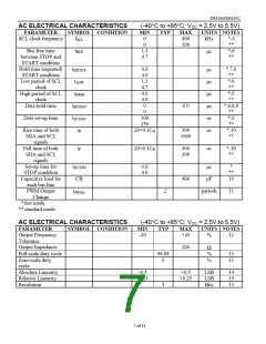
AC ELECTRICAL CHARACTERISTICS
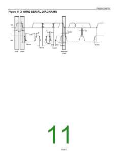
(-40°C to +85°C; VCC = 2.5V to 5.5V)
PARAMETER
SYMBOL CONDITION
MIN
0
TYP
MAX
400
UNITS NOTES
SCL clock frequency
fSCL
kHz
*,6
**
0
100
Bus free time
between STOP and
START condition
Hold time (repeated)
START condition
Low period of SCL
clock
tBUF
1.3
4.7
*,6
**
µs
tHD:STA
tLOW
0.6
4.0
1.3
4.7
0.6
4.0
0
0
*,7,6
**
*,6
**
*,6
**
*,6,8,9
**
*,6
**
µs
µs
µs
µs
ns
ns
High period of SCL
clock
tHIGH
tHD:DAT
tSU:DAT
tR
Data hold time
0.9
Data set-up time
100
250
20+0.1CB
Rise time of both
SDA and SCL
signals
300
1000
*,10
**
Fall time of both
SDA and SCL
signals
tF
20+0.1CB
300
300
ns
*,10
**
Set-up time for
STOP condition
Capacitive load for
each bus line
PWM Output
Change
tSU:STO
CB
0.6
4.0
*
**
10
µs
pF
400
2
periods
11
tPWMο
*fast mode
**standard mode
AC ELECTRICAL CHARACTERISTICS
(-40°C to +85°C; VCC = 2.5V to 5.5V)
PARAMETER
Output Frequency
Tolerance
SYMBOL CONDITION
MIN
TYP
MAX
UNITS NOTES
-20
+20
%
12
Output Impedance
Full-scale duty cycle
Zero-scale duty
cycle
200
Ω
%
%
96.88
0
13
13
Absolute Linearity
Relative Linearity
Resolution
-0.5
-0.25
+0.5
+0.25
LSB
LSB
Bits
14
15
13
5
7 of 11

 DALLAS [ DALLAS SEMICONDUCTOR ]