DS1050/DS1052
The device is ideal for low cost LCD contrast and/or brightness control, power supply voltage adjustment,
battery charging or current adjustment. The DS1050/DS1052 is offered in standard integrated circuit
packaging including the 8-L DIP, 8-L (150 mil) SOIC, and the space saving 8-L (118 mil) µSOP.
OPERATION
Interface protocol is simplified to an 8-bit control byte and 8-bit data-byte. Information can be read or
written to the DS1050/DS1052 including a commanded shutdown operation.
Power-up Configuration
The DS1050/DS1052 powers-up to half-scale (10000B) providing 50% duty-cycle. Once powered, the
PWM output can be changed via the 2-wire addressable serial port.
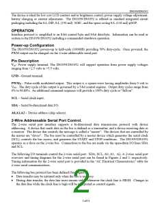
Pin Description
Vcc- Power supply terminal. The DS1050/DS1052 will support operation from power supply voltages
ranging from +2.5 volts to +5.5 volts.
GND - Ground terminal.
PWMO – Pulse-width modulated output. This output is a square-wave having amplitudes from 0 volt to
VCC. The duty cycle of this output is governed by a 5-bit control register. Output duty cycles range from
0% to 96.88%. An additional command sequence will provide a 100% duty cycle or “full-on”.
SCL – Serial clock input.
SDA – Serial bi-directional data I/O.
A0,A1,A2 - Device address (chip selects).
2-Wire Addressable Serial Port Control.
The 2-wire serial port interface supports a bi-directional data transmission protocol with device
addressing. A device that sends data on the bus is defined as a transmitter, and a device receiving data as
a receiver. The device that controls the message is called a "master". The devices that are controlled by
the master are "slaves". The bus must be controlled by a master device which generates the serial clock
(SCL), controls the bus access, and generates the START and STOP conditions. The DS1050/DS1052
operates as a slave on the 2-wire bus. Connections to the bus are made via the open-drain I/O lines SDA
and SCL.
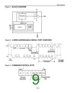
The following I/O terminals control the 2-wire serial port: SDA, SCL, A0, A1, A2. A 2-wire serial port
overview and timing diagrams for the 2-wire serial port can be found in Figures 2 and 3, respectively.
Timing information for the 2-wire serial port is provided in the “AC Electrical Characteristics” table for
2-wire serial communications.
The following bus protocol has been defined (See Figure 2).
•
•
Data transfer may be initiated only when the bus is not busy.
During data transfer, the data line must remain stable whenever the clock line is HIGH. Changes in
the data line while the clock line is high will be interpreted as control signals.
2 of 11

 DALLAS [ DALLAS SEMICONDUCTOR ]