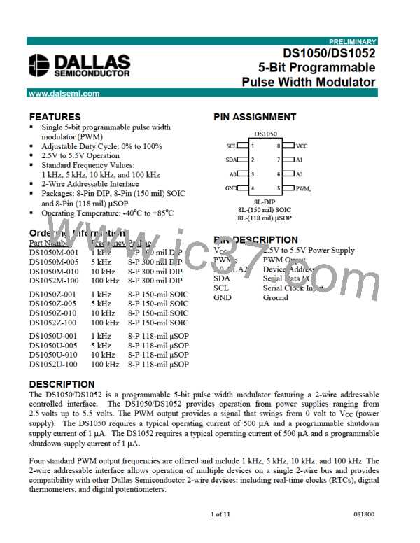
DS1050/DS1052
Figure 1 BLOCK DIAGRAM
vcc
OSCILLATOR
DRIVER
PWMΟ
CONTROL LOGIC
SCL
SDA
SHUTDOWN
CONTROL
CIRCUITRY
Serial Port
A0
A1
A2
GND
Figure 2 2-WIRE ADDRESSABLE SERIAL PORT OVERVIEW
SDA
msb
slave address
r/w
direction
bit
acknowledgement
signal fromreceiver
acknowledgement
signal fromreceiver
SCL
3-7
1
1
2
6
7
8
9
2
8
9
ACK
ACK
Start
Condition
Stop Condition
or repeated
Start Condition
repeatedif more bytes
are transferred
Figure 3 COMMAND/CONTROL BYTE
msb
lsb
r/w
A0
0
1
0
1 A2 A1
Device
Identifier
Device
Address
Read/Write
Bit
9 of 11

 DALLAS [ DALLAS SEMICONDUCTOR ]