39
8Bit Single Chip Microcontroller
DMC73C168
Write
Read
Enable Latch
INT FLAG
INPUT
D
Q
INT
D
CLR
Q
AND
Read
INPUT
Interrupt Flag
FLAG READ
FLAG READ
INT Enable
INT Enable
OR
D
Q
Interrupt Flag
INT Request
INT
D
CLR
Q
AND
INPUT
INT FLAG
CLEAR
D
Q
Enable Latch
Write
Read
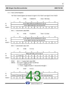
Note) INT4-0 : INT4 External
INT4-1 : INT4 A/D Converter
Figure 5-4A-2. Interrupt 4 Logic
To even further conserve the already low power requirement, two low power modes are provided. These
modes are called Halt and Wake up and entered by executing a IDLE instruction. Either an external
interrupt or the timer interrupt will release the device from the low power depending on whether it is in
the Halt or Wake-up mode. See Section 5.12 for a complete description of the modes and interrupts.
When an external interrupt is first asserted, its level is gated into interrupt Flag. In order for an interrupt
signal to be detected the signal width must be a minimum of 5 internal clock cycles. The interrupt Flag
will be set to '1'. If INTn is removed before the interrupt is recognized, its occurrence is latched in by the
INTn Enable Flag. The INTn Enable bit is used separately to individually mask the interrupt levels. This
bit must be 1 before the interrupt to be recognized.
As previously stated, all interrupt control bits are implemented in the IOCTL0, IOCTL1 and IOCTL2
registers in the Peripheral File. I/O instructions may simply read from and write to each INTn Enable
bit. By the INTn input, the interrupt Flag is set to one at falling edge and become active through interrupt
is enabled. The interrupt service routine is executed after the currently executing instruction is completed.
the value of the Status Register and Program Counter (MSB and LSB) respectively moves onto the stack
and zeros the Status Register (see Section 4.3). The corresponding vector address is loaded into the
Program Counter and interrupt service routine is executed. The corresponding interrupt Flag is
automatically cleared. (But INT4F, INT40F, INT41F flags are not automatically cleared, because they
used same interrupt vector address. These flags are cleared by only program.)
The External interrupts, INT1, INT3 and INT4-0 have schmitt Trigger inputs and can be used as zero-
cross detector.
The following attention have to be paid due to using both as the External interrupt pins and general
purpose I/O pins.
£Ä£Á£Å£×£Ï £Ï
DAEWOO ELECTRONICS CO., LTD.

 DAEWOO [ DAEWOO Electronic Components ]