ES51963
4 1/2 DMM
Cint
input
signal
Buf
reference
voltage
integrator
output
BufX10
input signal < 0
input signal > 0
different
input
integration
time
fixed slope
fixed slope
different
input
integration
time
Fixed
integration deintegration
time time
Variable
Fixed
integration deintegration
time time
Variable
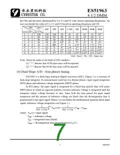
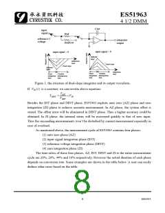
Figure 1. the structure of dual-slope integrator and its output waveform.
If VIN (t) is a constant, we can rewrite above equation:
TINT
VREF
TDINT
=
×VIN
Besides the INT phase and DINT phase, ES51963 exploits auto zero (AZ) phase and zero
integration (ZI) phase to achieve accurate measurement. In AZ phase, the system offset is
stored. The offset error will be eliminated in DINT phase. Thus a higher accuracy could be
obtained. In ZI phase, the internal status will be recovered quickly to that of zero input.
Thus the succeeding measurements won’t be disturbed by current measurement especially in
case of overload.
As mentioned above, the measurement cycle of ES51963 contains four phases:
(1) auto zero phase (AZ)
(2) input signal integration phase (INT)
(3) reference voltage integration phase (DINT)
(4) zero integration phase (ZI)
The time ratios of these four phases, AZ, INT, DINT and ZI to the entire measurement
cycle are 20%, 20%, 44% and 16% respectively. However the actual duration of each phase
depends on conversion rate. Some examples are shown in the table below. A user can easily
deduce other cases based on the table.
8
2003/9/1

 CYRUSTEK [ Cyrustek corporation ]