ES51963
4 1/2 DMM
(7) Zero Calibration
For ES51963 the A-to-D output might have an offset value due to internal delay. The
amount of offset depends on conversion rate and external components: Vref, Rint and Cint.
However as external components in application board are fixed. The offset will be constant. To
eliminate this offset error ES51963 provides zero calibration. To perform zero calibration, the
microprocessor should send a status word with ZERO bit as high with mode 1 communication.
As ES51963 receives the status word it will short the Vin+ and Vin- (zero input) internally and
sends eight measured values to microprocessor. The ZERO bit of the status associated with these
zero input count will be high. It is recommended to let the microprocessor remember the last zero
input count (Zero8) among the eight data. The offset error can be eliminated by subtracting the
zero input count from the subsequent measurements. Hence zero calibration should be executed
before normal conversion measurement.
It is worthy to note that ES51963 will leave zero calibration mode as it completes eight
zero input measurements which means that the microprocessor need not to send another status to
cancel calibration mode. In addition, as the offset value depends on conversion rate, zero
calibration should be performed as long as the conversion rate changes.
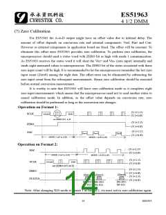
Operation on Format 1:
(V-)+2.1V
(V-)+0.8V
SCLK
START
END
set ZERO (S7) to H
(V-)+2.1V
(V-)+0.8V
ZERO
EOC
(V-)+2.1V
(V-)+0.8V
Zero1
Zero2
Zero8
MODE 2 (uP to A/D)
MODE 1 (A/D to uP)
Operation on Format 2:
(V-)+2.1V
(V-)+0.8V
EOC
MODE 2 (uP to A/D)
MODE 1 (A/D to uP)
(V-)+2.1V
(V-)+0.8V
SCLK
START
END
set ZERO (S7) to H
(V-)+2.1V
(V-)+0.8V
(V-)+2.1V
ZERO
(Zero8)
(Zero1) (Zero2)
STATUS
(V-)+0.8V
D0~D15
S0~S15
D0~D15
S0~S15
D0~D15
S0~S15
Note: After changing X10 mode at format 1 or format 2, we must active zero calibration again.
14
2003/9/1

 CYRUSTEK [ Cyrustek corporation ]