PSoC® 3: CY8C32 Family
Data Sheet
I2C provides hardware address detect of a 7-bit address without
CPU intervention. Additionally the device can wake from
low-power modes on a 7-bit hardware address match. If wakeup
functionality is required, I2C pin connections are limited to the
two special sets of SIO pins.
SMBus operation (through firmware support – SMBus
supported in hardware in UDBs)
7-bit hardware address compare
Wake from low-power modes on address match
I2C features include:
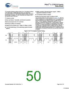
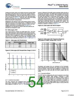
Data transfers follow the format shown in Figure 7-20. After the
START condition (S), a slave address is sent. This address is 7
bits long followed by an eighth bit which is a data direction bit
(R/W) - a 'zero' indicates a transmission (WRITE), a 'one'
indicates a request for data (READ). A data transfer is always
terminated by a STOP condition (P) generated by the master.
However, if a master still wishes to communicate on the bus, it
can generate a repeated START condition (Sr) and address
another slave without first generating a STOP condition. Various
combinations of read/write formats are then possible within such
a transfer.
Slave and Master, Transmitter, and Receiver operation
Byte processing for low CPU overhead
Interrupt or polling CPU interface
Support for bus speeds up to 1 Mbps (3.4 Mbps in UDBs)
7 or 10-bit addressing (10-bit addressing requires firmware
support)
Figure 7-20. I2C Complete Transfer Timing
SDA
SCL
8
9
1 - 7
8
9
1 - 7
8
9
1 - 7
START
Condition
STOP
Condition
ADDRESS
R/W
ACK
DATA
ACK
DATA
ACK
Document Number: 001-56955 Rev. *J
Page 50 of 119
[+] Feedback

 CYPRESS [ CYPRESS ]