PSoC® 3: CY8C32 Family
Data Sheet
to any device pin and any internal digital signal accessible
through the DSI. Each of the four instances has a compare
output, terminal count output (optional complementary compare
output), and programmable interrupt request line. The
Timer/Counter/PWMs are configurable as free running, one shot,
or Enable input controlled. The peripheral has timer reset and
capture inputs, and a kill input for control of the comparator
outputs. The peripheral supports full 16-bit capture.
7.5 USB
PSoC includes a dedicated Full-Speed (12 Mbps) USB 2.0
transceiver supporting all four USB transfer types: control,
interrupt, bulk, and isochronous. PSoC Creator provides full
configuration support. USB interfaces to hosts through two
dedicated USBIO pins, which are detailed in the “I/O System and
Routing” section on page 34.
USB includes the following features:
Timer/Counter/PWM features include:
16-bit Timer/Counter/PWM (down count only)
Selectable clock source
Eight unidirectional data endpoints
One bidirectional control endpoint 0 (EP0)
Shared 512-byte buffer for the eight data endpoints
Dedicated 8-byte buffer for EP0
PWM comparator (configurable for LT, LTE, EQ, GTE, GT)
Period reload on start, reset, and terminal count
Interrupt on terminal count, compare true, or capture
Dynamic counter reads
Three memory modes
Manual Memory Management with No DMA Access
Manual Memory Management with Manual DMA Access
Automatic Memory Management with Automatic DMA
Access
Timer capture mode
Count while enable signal is asserted mode
Free run mode
Internal 3.3 V regulator for transceiver
Internal 48 MHz main oscillator mode that auto locks to USB
bus clock, requiring no external crystal for USB (USB equipped
parts only)
One Shot mode (stop at end of period)
Complementary PWM outputs with deadband
PWM output kill
Interrupts on bus and each endpoint event, with device wakeup
USB Reset, Suspend, and Resume operations
Bus powered and self powered modes
Figure 7-18. USB
Figure 7-19. Timer/Counter/PWM
Clock
Reset
Enable
Capture
Kill
IRQ
Timer / Counter /
PWM 16-bit
TC / Compare!
Compare
512 X 8
Arbiter
SRAM
External 22 Ω
Resistors
D+
S I E
(Serial Interface
Engine)
USB
I/O
2
7.7 I C
D–
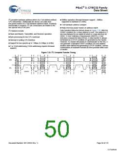
The I2C peripheral provides a synchronous two wire interface
designed to interface the PSoC device with a two wire I2C serial
communication bus. The bus is compliant with Philips ‘The I2C
Specification’ version 2.1. Additional I2C interfaces can be
instantiated using Universal Digital Blocks (UDBs) in PSoC
Creator, as required.
Interrupts
48 MHz
IMO
7.6 Timers, Counters, and PWMs
To eliminate the need for excessive CPU intervention and
overhead, I2C specific support is provided for status detection
and generation of framing bits. I2C operates as a slave, a master,
or multimaster (Slave and Master). In slave mode, the unit
always listens for a start condition to begin sending or receiving
data. Master mode supplies the ability to generate the Start and
Stop conditions and initiate transactions. Multimaster mode
provides clock synchronization and arbitration to allow multiple
masters on the same bus. If Master mode is enabled and Slave
mode is not enabled, the block does not generate interrupts on
externally generated Start conditions. I2C interfaces through the
DSI routing and allows direct connections to any GPIO or SIO
pins.
The Timer/Counter/PWM peripheral is a 16-bit dedicated
peripheral providing three of the most common embedded
peripheral features. As almost all embedded systems use some
combination of timers, counters, and PWMs. Four of them have
been included on this PSoC device family. Additional and more
advanced functionality timers, counters, and PWMs can also be
instantiated in Universal Digital Blocks (UDBs) as required.
PSoC Creator allows you to choose the timer, counter, and PWM
features that they require. The tool set utilizes the most optimal
resources available.
The Timer/Counter/PWM peripheral can select from multiple
clock sources, with input and output signals connected through
the DSI routing. DSI routing allows input and output connections
Document Number: 001-56955 Rev. *J
Page 49 of 119
[+] Feedback

 CYPRESS [ CYPRESS ]