PSoC® 3: CY8C32 Family
Data Sheet
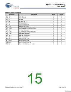
4.3.1.5 Program Branching Instructions
The 8051 supports a set of conditional and unconditional jump instructions that help to modify the program execution flow. Table 4-5
shows the list of jump instructions.
Table 4-5. Jump Instructions
Mnemonic
ACALL addr11
Description
Bytes
Cycles
Absolute subroutine call
Long subroutine call
Return from subroutine
Return from interrupt
Absolute jump
2
3
1
1
2
3
2
1
2
2
3
3
3
3
2
3
1
4
4
4
4
3
4
3
5
4
4
5
4
4
5
4
5
1
LCALL addr16
RET
RETI
AJMP addr11
LJMP addr16
SJMP rel
Long jump
Short jump (relative address)
JMP @A + DPTR
JZ rel
Jump indirect relative to DPTR
Jump if accumulator is zero
JNZ rel
Jump if accumulator is nonzero
CJNE A,Direct, rel
CJNE A, #data, rel
CJNE Rn, #data, rel
CJNE @Ri, #data, rel
DJNZ Rn,rel
DJNZ Direct, rel
NOP
Compare direct byte to accumulator and jump if not equal
Compare immediate data to accumulator and jump if not equal
Compare immediate data to register and jump if not equal
Compare immediate data to indirect RAM and jump if not equal
Decrement register and jump if not zero
Decrement direct byte and jump if not zero
No operation
Simultaneous CPU and DMA access to peripherals located on
different spokes
4.4 DMA and PHUB
The PHUB and the DMA controller are responsible for data
transfer between the CPU and peripherals, and also data
transfers between peripherals. The PHUB and DMA also control
device configuration during boot. The PHUB consists of:
Simultaneous DMA source and destination burst transactions
on different spokes
Supports 8, 16, 24, and 32-bit addressing and data
A central hub that includes the DMA controller, arbiter, and
router
Table 4-6. PHUB Spokes and Peripherals
Multiple spokes that radiate outward from the hub to most
peripherals
PHUB Spokes
Peripherals
0
1
2
SRAM
There are two PHUB masters: the CPU and the DMA controller.
Both masters may initiate transactions on the bus. The DMA
channels can handle peripheral communication without CPU
intervention. The arbiter in the central hub determines which
DMA channel is the highest priority if there are multiple requests.
IOs, PICU, EMIF
PHUB local configuration, Power manager,
Clocks, IC, SWV, EEPROM, Flash
programming interface
3
4
5
6
7
Analog interface and trim, Decimator
USB, USB, I2C, Timers, Counters, and PWMs
Reserved
4.4.1 PHUB Features
CPU and DMA controller are both bus masters to the PHUB
UDBs group 1
Eight Multi-layer AHB Bus parallel access paths (spokes) for
peripheral access
UDBs group 2
Document Number: 001-56955 Rev. *J
Page 16 of 119
[+] Feedback

 CYPRESS [ CYPRESS ]