CY8C24x23 Final Data Sheet
3. Electrical Specifications
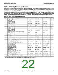
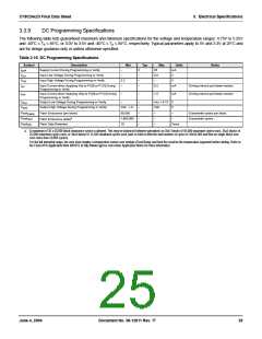
3.3.5
DC Switch Mode Pump Specifications
The following table lists guaranteed maximum and minimum specifications for the voltage and temperature ranges: 4.75V to 5.25V
and -40°C ≤ T ≤ 85°C, or 3.0V to 3.6V and -40°C ≤ T ≤ 85°C, respectively. Typical parameters apply to 5V and 3.3V at 25°C and
A
A
are for design guidance only or unless otherwise specified.
Table 3-10. DC Switch Mode Pump (SMP) Specifications
Symbol
Description
Min
4.75
Typ
5.0
Max
5.25
Units
Notes
V
V
5V
3V
5V Output voltage
3V Output voltage
V
V
Average, neglecting ripple
PUMP
PUMP
PUMP
3.00
3.25
3.60
Average, neglecting ripple
I
Available Output Current
For implementation, which includes 2 uH induc-
tor, 1 uF cap, and Schottky diode.
V
V
= 1.5V, V
= 1.8V, V
= 3.25V
= 5.0V
8
5
–
–
–
–
mA
mA
BAT
BAT
PUMP
PUMP
V
V
V
5V
Input Voltage Range from Battery
1.8
1.0
1.1
–
–
–
–
5
5.0
3.3
–
V
V
V
BAT
3V
Input Voltage Range from Battery
BAT
Minimum Input Voltage from Battery to Start Pump
BATSTART
a
a
∆V
∆V
Line Regulation (over V
Load Regulation
range)
–
PUMP_Line
PUMP_Load
PUMP_Ripple
BAT
%V
%V
O
O
–
5
–
∆V
Output Voltage Ripple (depends on cap/load)
Efficiency
–
25
50
–
–
mVpp
%
Configuration of note 2, load is 5mA.
–
35
Configuration of note 2, load is 5mA, Vout is
3.25V.
F
Switching Frequency
Switching Duty Cycle
–
–
1.3
50
–
–
MHz
%
PUMP
DC
PUMP
a. V is the “Vdd Value for PUMP Trip” specified by the VM[2:0] setting in the DC POR and LVD Specification, Table 3-14 on page 24.
O
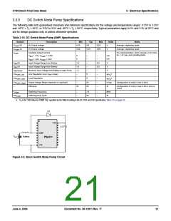
D1
Vdd
C1
SMP
+
VBAT
TM
Battery
PSoC
Vss
Figure 3-2. Basic Switch Mode Pump Circuit
June 4, 2004
Document No. 38-12011 Rev. *F
21

 CYPRESS [ CYPRESS ]