CY7C9689
and Encoder are enabled, the input FIFO may be loaded at any
rate supported by the FIFO (up to 50 MHz), without generating
any decoder errors at the receive end of the link.
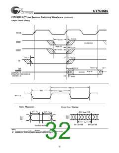
The Violation (VLTN) output indicates a code violation has oc-
cured. When the VLTN output is asserted HIGH, this indicates
a transmission error is detected in the character at the current
transfer clock cycle.
CY7C9689 TAXI HOTLink Receive-Path
Operating Mode Descriptions
Synchronous Undecoded
In this mode, both the Receive FIFO and the 5B/4B, 6B/5B
Decoder are bypassed, and data passes directly from the De-
serializer to the output register. The Deserializer operates syn-
chronous to the recovered bit-clock, which is divided by 10 to
generate the output RXCLK clock. In this mode the RXRST
input is not interpreted and may be biased either HIGH or
LOW.
The HOTLink Receiver can be configured into several operat-
ing modes, each providing different capabilities and fitting dif-
ferent reception needs. These modes are selected using the
FIFOBYP, ENCBYP, BYTE8/10 inputs on the CY7C9689
Transceiver. These modes can be reduced to four primary
classes:
•Synchronous Decoded
•Synchronous Undecoded
•Asynchronous Decoded
•Asynchronous Undecoded
This mode is usually used for products containing external de-
coders or descramblers that must meet specific protocol re-
quirements. New data is provided at the RXDATA outputs once
every rising edge of RXCLK. Received characters are not
checked for any specific coding requirements and no decoding
errors are reported.
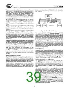
In all these modes, serial data is received at one of the differ-
ential line receiver inputs and routed to the Deserializer and
Framer. The PLL in the clock and data recovery block is used
to extract a bit-rate clock from the transitions in the data
stream, and uses that clock to capture bits from the serial
stream. These bits are passed to the Deserializer where they
are formed into 10- or 12-bit characters.
Asynchronous Decoded
In Asynchronous Decoded mode, both the Receive FIFO and
the Decoder of the CY7C9689 are enabled. The deserializer
operates synchronous to the recovered bit-clock, which is di-
vided by 10 to generate the Receive FIFO write clock. Charac-
ters are read from the Receive FIFO, using the external
RXCLK input, when addressed by CE and selected by RXEN.
In this mode the RXRST input is interpreted.
To align the incoming bit stream to the proper character bound-
aries, the Framer must be enabled by asserting RFEN HIGH.
The Framer logic-block checks the incoming bit stream for the
unique pattern that defines the character boundaries. This log-
ic filter looks for the JK or LM (when BYTE8/10 is LOW) sync
character. Once a sync character is found, the Framer cap-
tures the offset of the data stream from the present character
boundaries, and resets the boundary to reflect this new offset,
thus framing the data to the correct character boundaries.
Asynchronous Decoded mode supports the same Output
Register mapping as the Synchronous Decoded mode. Be-
cause both the Receive FIFO and Decoder are enabled, the
output FIFO may be read at any rate supported by the FIFO,
however, if the Receive FIFO ever indicates a full condition
(RXFULL is asserted), data may be lost.
Since noise induced errors can cause the incoming data to be
corrupted, and since many combinations of corrupt and legal
data can create an aliased sync character, the framer may also
be disabled by deasserting RFEN LOW.
Asynchronous Undecoded
In Asynchronous Undecoded modes, the Receive FIFO is en-
abled. This means that all characters received from the serial
interface are written to the Receive FIFO before being passed
to the output register. The Deserializer operates synchronous
to the recovered bit-clock, which is divided by 10 (or 12) to
generate the Receive FIFO write clock. Data is read from the
Receive FIFO, using the RXCLK input clock, when addressed
by CE and selected by RXEN.
Synchronous Decoded
In these modes, the Receive FIFO is bypassed, while the
5B/4B, 6B/5B Decoder is enabled. Framed characters output
from the Deserializer are decoded, and passed directly to the
Receive Output Register. The Deserializer operates synchro-
nous to the recovered bit-clock, which is divided by 10, gener-
ate the output RXCLK clock. In this mode the RXRST input is
not interpreted and may be biased either HIGH or LOW.
These modes are usually used for products containing exter-
nal decoders or descramblers, that must meet specific protocol
requirements. New data may be read from the Receive FIFO
any time that the FIFO status flags indicate a non-empty con-
dition (RXEMPTY is deasserted). To ensure that data is not
lost, the Receive FIFO must be read faster than data is loaded
into the Receive FIFO.
These modes are usually used for products that must meet
specific protocol requirements. New decoded characters are
provided at the RXDATA outputs once every rising edge of
RXCLK. If RXEMPTY is asserted LOW, the characters on the
RXCMD output register is a JK or LM sync character, and the
discard policy is set to non-0. Because the decoder is now
enabled, all received characters are checked for compliance to
the 4B/5B decoding rules.
If the receiver is to provide framed characters, it is necessary
for the transmit end to include JK or LM sync characters in the
data stream. This can be done by:
•operating the transmitter in encoded mode and writing JK or
LM characters into the data stream,
Output Register Mapping
•operating the transmitter in pre-encoded mode and writing
the 10-bit value for an encoded JK (1100010001) or LM
(011000100011) character to the data stream
•not enabling the transmitter when it is operated in synchro-
nousmode, orby allowing the transitFIFO to goempty when
it is operated in asynchronous mode.
The RXDATA[11:0] output bus is mapped into a character con-
sisting of eight bits of data and four bits of command, or ten
bits of data and two bits of command. An accompanying
RXSC/D bit identifies the character as either command or
data.
36

 CYPRESS [ CYPRESS ]