CY7C9689
Synchronous Encoded
Functional Description
In this mode, the Transmit FIFO is bypassed, while the 4B/5B,
5B/6B encoder is enabled. One character is accepted at the
Transmit Input Register at the rising edge of REFCLK, and
passed to the Encoder where it is encoded for serial transmis-
sion. The Serializer operates synchronous to REFCLK, which
is multiplied by 10 or 5 to generate the serial data bit-clock. In
this mode the TXRST and TXHALT inputs are not interpreted
and may be tied either HIGH or LOW. To place the CY7C9689
into synchronous modes, FIFOBYP must be LOW.
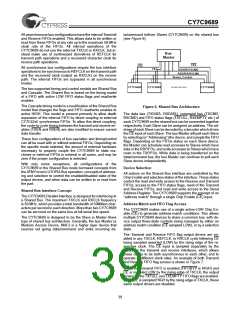
The interconnection of two or more CY7C9689 Transceivers
forms a general-purpose communications subsystem capable
of transporting user data at up to 20 MBytes per second over
several types of serial interface media. The CY7C9689 is high-
ly configurable with multiple modes of operation.
In the transmit section of the CY7C9689, data moves from the
input register, through the Transmit FIFO, to the 4B/5B Encod-
er. The encoded data is then shifted serially out the OUTx±
differential PECL compatible drivers. The bit-rate clock is gen-
erated internally from a 2.5x, 5x, or 10x PLL clock multiplier. A
more complete description is found in the section CY7C9689
HOTLink Transmit-Path Operating Mode Description.
This mode is usually used for products that must meet specific
predefined protocol requirements, and cannot tolerate the un-
controlled insertion of SYNC fill characters. The host system
is required to provide new data at every rising edge of REFCLK
(along with TXEN) to maintain the data stream. If TXEN is not
asserted, the Encoder is loaded with JK or LM sync charac-
ters.
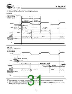
In the receive section of the CY7C9689, serial data is sampled
by the receiver on one of the INx± differential line receiver in-
puts. The receiver clock and data recovery PLL locks onto the
selected serial bit stream and generates an internal bit-rate
sample clock. The bit stream is deserialized, decoded, and
presented to the Receive FIFO, along with a character clock.
The data in the FIFO can then be read either slower or faster
than the incoming character rate. A more complete description
is found in the section CY7C9689 HOTLink Receive-Path Op-
erating Mode Description.
Input Register Mapping
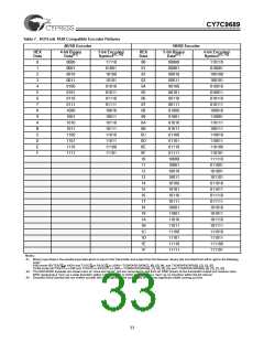
In Encoded modes, the bits of the TXDATA input bus are
mapped into characters (as shown in Table 1), including a
TXSVS bit, eight bits of data, and a TXSC/D bit to select either
Special Character codes or Data characters.
The TXSC/D bit controls the encoding of the TXDATA[7:0] or
TXDATA[9:0] bits of each character. It is used to identify if the
input character represents a Data Character or a Special
Character code. If TXSC/D is LOW, the character appeared on
the TXDATA bus is encoded using the Data Character codes
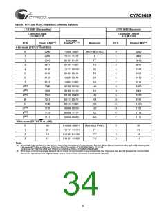
listed in Table 7. If TXSC/D is HIGH, the character on the TX-
CMD bus is encoded using the Special Character codes listed
in Table 8.
The Transmitter and Receiver parallel interface timing and
functionality can be configured to Cascade directly to external
FIFOs for depth expansion, couple directly to registers, or cou-
ple directly to state machines. These interfaces can accept or
output either:
•8-bit characters
•10-bit characters
•10-bit pre-encoded characters (pre-scrambled or
pre-encoded)
Synchronous Pre-encoded
In synchronous pre-encoded mode, both the Transmit FIFO
and the 4B/5B encoder are bypassed, and data passes direct-
ly from the Transmit Input Register to the Serializer. The Seri-
alizer operates synchronous to REFCLK, which is multiplied
by 10 or 5 when BYTE8/10 is HIGH (as selected by the SPD-
SEL and RANGESEL inputs) to generate the serial data bit-
clock. In this mode, part of the TXCMD bus inputs are used as
part of the data input bus. To place the CY7C9689 into syn-
chronous modes, FIFOBYP must be LOW.
•12-bit pre-encoded characters (pre-scrambled or
pre-encoded)
The bit numbering and content of the parallel transmit interface
is shown in Table 1. When operated with the 8B/10B Encoder
bypassed, the TXSC/D and RXSC/D bits are ignored.
The HOTLink Transceiver serial interface provides a seamless
interface to various types of media. A minimal number of ex-
ternal passive components are required to properly terminate
transmission lines and provide LVPECL loads. For power sup-
ply decoupling, a single capacitor (in the range of 0.02 mF to
0.1 mF) is required per power/ground pair. Additional informa-
tion on interfacing these components to various media can be
found in the HOTLink Design Considerations application note.
This mode is usually used for products containing external en-
coders or scramblers, that must meet specific protocol require-
ments. The host system is required to provide new data at
every rising edge of the REFCLK (along with TXEN) to main-
tain the data stream. If TXEN is not asserted, the Serializer is
loaded with JK or LM sync characters.
CY7C9689 TAXI HOTLink Transmit-Path
Operating Mode Descriptions
In this mode the LSB of each input character (TXDATA[0]) is
shifted out first, followed sequentially by TXDATA[1] through
TXDATA[9] (TXDATA[11] when BYTE8/10 is LOW).
The TAXI HOTLink Transmitter can be configured into several
operating modes, each providing different capabilities and fit-
ting different transmission needs. These modes are selected
using the FIFOBYP, ENCBYP and BYTE8/10 inputs on the
CY7C9689 Transceiver. These modes can be reduced to five
primary classes:
Asynchronous Encoded
In Asynchronous Encoded mode, both the Transmit FIFO and
the Encoder are enabled. This provides 256 characters of data
buffering. The Serializer operates synchronous to REFCLK,
which is multiplied by 2.5, 5, or 10 to generate the serial data
bit-clock (as selected by SPDSEL and RANGESEL). In this
mode the TXRST and TXHALT inputs are interpreted.
•Synchronous Encoded
•Synchronous Pre-encoded
•Asynchronous Encoded
•Asynchronous Pre-encoded
This mode supports the same Input Register mapping as Syn-
chronous Encoded mode. Because both the Transmit FIFO
35

 CYPRESS [ CYPRESS ]