CY7C9689
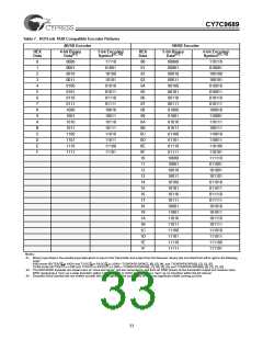
Table 7. HOTLink TAXI Compatible Encoder Patterns
4B/5B Encoder
5B/6B Encoder
5-bit Binary
HEX
Data
4-bit Binary
5-bit Encoded
HEX
Data
6-bit Encoded
[41]
[42, 43]
[41]
[42, 43]
Data
Symbol
Data
Symbol
0
1
2
3
4
5
6
7
8
9
A
B
C
D
E
F
0000
0001
0010
0011
0100
0101
0110
0111
1000
1001
1010
1011
1100
1101
1110
1111
11110
01001
10100
10101
01010
01011
01110
01111
10010
10011
10110
10111
11010
11011
11100
11101
00
01
02
03
04
05
06
07
08
09
0A
0B
0C
0D
0E
0F
10
11
12
13
14
15
16
17
18
19
1A
1B
1C
1D
1E
1F
00000
00001
00010
00011
00100
00101
00110
00111
01000
01001
01010
01011
01100
01101
01110
01111
10000
10001
10010
10011
10100
10101
10110
10111
10001
11001
11010
11011
11100
11101
11110
11111
110110
010001
100100
100101
010010
010011
010110
010111
100010
110001
110111
100111
110010
110011
110100
110101
111110
011001
101001
101101
011010
011011
011110
011111
101010
101011
101110
101111
111010
111011
111100
111101
Notes:
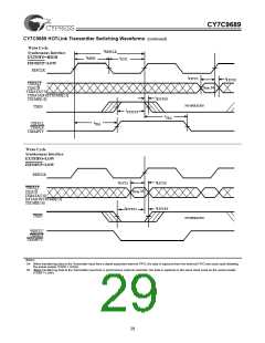
41. Binary Input Data is the parallel input data which is input to the Transmitter and output from the Receiver. Binary bits are listed from left to right in the following
order:
8-Bit mode (BYTE8/10 is HIGH and TXSC/D or RXSC/D is LOW)—TXDATA/RXDATA[7], [6], [5], [4], and TXDATA/RXDATA[3], [2], [1], [0].
10-Bit mode (BYTE8/10 is LOW and TXSC/D or RXSC/D is LOW)—TXDATA/RXDATA[8], [7], [6], [5], [4], and TXDATA/RXDATA[9], [3], [2], [1], [0].
42. The ENCODED Symbols are shown here as “ones and zeros”, but are converted to and from an NRZI stream at the transmitter output and receiver input.
NRZI represents a “one” as a state transition (either LOW-to-HIGH or HIGH-to-LOW) and a “zero” as no transition within the bit interval.
43. Encoded Serial Symbol bits are shifted out with the most significant bit (Left-most) of the most significant nibble coming out first.
33

 CYPRESS [ CYPRESS ]